Facebook
 Google
 GitHub
 Linkedin
Hi,
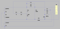
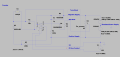
I've reverse engineered the crowbar circuit on a large amplifier I'm working on. I understand the basics of how a crowbar is supposed to work, but this particular design is difficult for me to grasp. The input voltage is +/-250 VDC. The K1 relay appears to disable the crowbar when the relay coil is energized. I am trying to figure out how the crowbar is triggered. It looks to me like the relay must be in it's 'OFF' state to power the SCR. Any help is appreciated.
Schematic from LTSpice is attached.
Thanks,
Attachments
-
 123.9 KB Views: 31