Amplifier application

Johnfoxwell

Joined May 23, 2021
18
Hi everyone! I hope this section of the forum is the correct one for the question I am about to ask.

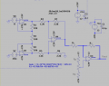
I should make a circuit that amplifies an analog signal [0 ... 500uV] into [0 ... 5V]. We have lm339n in the lab, but I read that it is a comparator and cannot be used as an amplifier, so I opted for an op07.
The questions I ask are twofold:

1) what op amp should I use for this purpose?
If you know of integrated circuits or modules that perform this task let me know

2) is the circuit I made (which I simulated and it works) ok?
I think using a 100kohm resistor and a 10 ohm resistor can be a problem as they have very different values.

Thank;)
The real problem is that you have not fully specified the problem. What frequency are you using? Or do you want to use a range of frequencies??
Operational amplifiers reduce their bandwidth as the gain increases.
The last amplifier in your circuit is just an inverter. Do you need the output to be in phase with the input ?

So many questions need to be answered. Without these you can’t check if your design meets the specification.
 

MrAl

Joined Jun 17, 2014
13,702
Hello again,

This next graph is a purely theoretical version not a simulation. It shows a similar response.
I may have lowered the value of C1 for these calculations i think to 0.005uf or 0.001uf, but it doesnt make much difference with that 100pf cap which makes the chip a sort of integrator so it has a regular rolloff. It's entirely possible C1 can be eliminated, but of course this has to be tested in real life with a real chip before using in any important application.
I dont think this is too unusual though because the internal structure is more like a high gain op amp and we know we can compensate op amps that dont have any built in compensation.
The circuit is the same as the previous post shows except for that value of C1.
Note a little difference in the high frequency response of the simulation vs this purely theoretical calculation.
I do wonder however if we can really get to over 10kHz bandwidth with a real life chip.


LM339-as-OpAmp_20220506-3.png
 

Thread Starter

luca290799

Joined Apr 4, 2022
60
Hello again,

Here is a simulation of a modified circuit.
Note this would have to be breadboarded to test completely.
Also note the slight gain change to make it 100, and a small input offset to center the AC sine output at 1/2 of Vcc.
The input is 10mv peak at 1kHz, sine.
In the AC plot the horizontal red line is the -3db point from max which is at 0Hz.


View attachment 266640
Hello! Sorry for my ignorance, I ask you a couple of information about the circuit:

- why did you insert R3, C2 and C1? Also I ask how you sized them.
- Why do you want to center the AC sine output at 1/2 VDC?
- Does it also work with a DC input?
 

MrAl

Joined Jun 17, 2014
13,702
Hello! Sorry for my ignorance, I ask you a couple of information about the circuit:

- why did you insert R3, C2 and C1? Also I ask how you sized them.
- Why do you want to center the AC sine output at 1/2 VDC?
- Does it also work with a DC input?

Hello there,

No problem really that's why we have these forums.

R3 is a pullup that is needed because the LM339 has no way to provide a positive output on it's own it can only sink current because the output is "open collector" and you can look that up on the web for more info.
C1 was recommended by the manufacturer in the app note.
C1 was later decreased in value and C2 was added to provide a better roll off response for stability.
The design still should be tested with a real IC chip and other parts to make sure it is stable as is.

The input was biased so that the output would be at 1/2 of Vcc. That allows for AC inputs.
For DC only inputs the biasing depends on what you need the output to do with a given range of DC inputs. If you need to use it with DC inputs then you can specify here and we can look at how it will work and if any modification is needed.
 

MrAl

Joined Jun 17, 2014
13,702
Hello again,

I took another quick look at this and found that there is reason to believe that C1 may be required in the circuit in order to muffle fast transients. You could scope out the real life circuit to find out what value would be good. C1 doesnt affect the average response much but it will probably affect the response to fast transients helping to keep the transient from affecting the circuit connected to the output.

Also, the approximate cut off frequency is w=1/(R1*C2).
 

Thread Starter

luca290799

Joined Apr 4, 2022
60
Ciao,

Nessun problema, ecco perché abbiamo questi forum.

R3 è un pullup necessario perché l'LM339 non ha modo di fornire un'uscita positiva da solo, può solo assorbire corrente perché l'uscita è "open collector" e puoi cercarla sul web per maggiori informazioni.
C1 è stato consigliato dal produttore nella nota dell'app.
C1 è stato successivamente ridotto di valore ed è stato aggiunto C2 per fornire una migliore risposta di roll-off per la stabilità.
Il design dovrebbe comunque essere testato con un vero chip IC e altre parti per assicurarsi che sia stabile così com'è.

L'ingresso è stato polarizzato in modo che l'uscita fosse a 1/2 di Vcc. Ciò consente ingressi CA.
Per gli ingressi solo CC, la polarizzazione dipende da ciò che l'uscita deve fare con un determinato intervallo di ingressi CC. Se è necessario utilizzarlo con ingressi CC, è possibile specificare qui e possiamo vedere come funzionerà e se sono necessarie modifiche.
[/CITAZIONE]

The DC input comes from a load cell (so it will be a differential input) and ranges from [2..24]mV. I want the output to be [0...5]V. I would like to figure out how to modify the circuit you posted so that it receives a differential input
 
Last edited:

Thread Starter

luca290799

Joined Apr 4, 2022
60
Hello again,

Here is a simulation of a modified circuit.
Note this would have to be breadboarded to test completely.
Also note the slight gain change to make it 100, and a small input offset to center the AC sine output at 1/2 of Vcc.
The input is 10mv peak at 1kHz, sine.
In the AC plot the horizontal red line is the -3db point from max which is at 0Hz.


View attachment 266640
I found some LM358s and tried this differential amplifier, it simulates well and I would like to create the PCB of it. Any advice/improvements?
Obviously I need a minimum tolerance of the resistors.

How can I remove the offset of about 0.5V that I have with this circuit?

LM358.jpg
 

Attachments

ericgibbs

Joined Jan 29, 2010
21,439
hi luca,
Now that you have successfully got your project working, and you intend creating a PCB to suit, it would help if you created a new thread on the PCBLayout Forum.

Mod.
 

Audioguru again

Joined Oct 21, 2019
6,826
Now you are using a lousy old LM358 opamp that has a high input offset voltage, very high noise level, crossover distortion and a poor slew rate that messes up above 2kHz at high levels.
 

MrAl

Joined Jun 17, 2014
13,702
I found some LM358s and tried this differential amplifier, it simulates well and I would like to create the PCB of it. Any advice/improvements?
Obviously I need a minimum tolerance of the resistors.

How can I remove the offset of about 0.5V that I have with this circuit?
Hello,

When you say 0.5v offset you mean output offset right?

All op amps have some input offset and with high gain that produces a high output offset. To get better offset you could use a chopper stabilized op amp or you could add an adjustment at the input of the op amp. For op amps that do not include offset adjust pins, you could form a voltage divider on one of the inputs on the op amp and provide just a tiny offset that counters the offset of the op amp.
The LM358 has max input offset of about 0.3mv i think, but it is quite stable over temperature so an adjustment network should help.

If you have trouble figuring out what the network has to look like just let me know i'll post something you can go by.

The LM358 is a work horse mostly suited for industrial applications but it also works in other apps including audio with some extra special attention to the circuit topology. Nothing very difficult though.
 

Thread Starter

luca290799

Joined Apr 4, 2022
60
Now you are using a lousy old LM358 opamp that has a high input offset voltage, very high noise level, crossover distortion and a poor slew rate that messes up above 2kHz at high levels.
If I could choose which integrated to use, I would definitely choose an AD623 (as was recommended to me). We have this in the lab, though, so we use this. Obviously this is a school project and not something that will be sold to the end consumer, so only educational purpose:D
 

Thread Starter

luca290799

Joined Apr 4, 2022
60
Hello,

When you say 0.5v offset you mean output offset right?

All op amps have some input offset and with high gain that produces a high output offset. To get better offset you could use a chopper stabilized op amp or you could add an adjustment at the input of the op amp. For op amps that do not include offset adjust pins, you could form a
Hello,

When you say 0.5v offset you mean output offset right?

All op amps have some input offset and with high gain that produces a high output offset. To get better offset you could use a chopper stabilized op amp or you could add an adjustment at the input of the op amp. For op amps that do not include offset adjust pins, you could form a voltage divider on one of the inputs on the op amp and provide just a tiny offset that counters the offset of the op amp.
The LM358 has max input offset of about 0.3mv i think, but it is quite stable over temperature so an adjustment network should help.

If you have trouble figuring out what the network has to look like just let me know i'll post something you can go by.

The LM358 is a work horse mostly suited for industrial applications but it also works in other apps including audio with some extra special attention to the circuit topology. Nothing very difficult though.
and provide just a tiny offset that counters the offset of the op amp.
The LM358 has max input offset of about 0.3mv i think, but it is quite stable over temperature so an adjustment network should help.

If you have trouble figuring out what the network has to look like just let me know i'll post something you can go by.

The LM358 is a work horse mostly suited for industrial applications but it also works in other apps including audio with some extra special attention to the circuit topology. Nothing very difficult though.
Yeah I mean offset output. I want the output [0 ... 5]V for [2m ... 24m]V input. But with this opamp, if I set input to 2mV, the output is approximately 500mV ... not 0V:confused:

I would be very interested in understanding the solutions to remove the offset, especially when you mentioned "voltage divider on one of the inputs on the op amp." I will look into the Internet or some university books because I think there are many good examples online, but in case of any questions and clarifications I will not hesitate to ask on this forum, you are really helping me a lot.

Should I open another thread for a question about offset or should I continue here?
 

MrAl

Joined Jun 17, 2014
13,702
Yeah I mean offset output. I want the output [0 ... 5]V for [2m ... 24m]V input. But with this opamp, if I set input to 2mV, the output is approximately 500mV ... not 0V:confused:

I would be very interested in understanding the solutions to remove the offset, especially when you mentioned "voltage divider on one of the inputs on the op amp." I will look into the Internet or some university books because I think there are many good examples online, but in case of any questions and clarifications I will not hesitate to ask on this forum, you are really helping me a lot.

Should I open another thread for a question about offset or should I continue here?

Hello again,

One thing you can try is to break R2 into two resistors, which then normally would be 90 Ohms each. Connect a 100k resistor to the center tap, then connect the other end of the resistor to something like +10v or -10v if necessary. However, the two 90 Ohm resistors than have to change.
So say the top resistor is R2a and the bottom is R2b. For a 1mv input offset then R2b would be something like 79.9 Ohms and R2a would be 180 minus that which comes out to about 100.09 Ohms. You might use a trim pot for that if you can find one of that total value 180 Ohms.

Since this is an instrumentation amplifier though you have to be willing to test for several specifications.
Of course the correct overall gain is one, but also the common mode rejection ratio. You dont want to turn this into an ordinary op amp.
This is true no matter what modification you make because these amps are designed to be more accurate than the typical op amp.

If you dont need super speed probably a chopper stabilized op amp would be better for the three IC sections. You may not be able to get theos though.

Of course you could try the 'extra' op amp solution with an extra op amp on the output with an offset adjust on the non inverting terminal. The gain would be just 1 so any input offset from that op will only appear on the output as that offset (only a gain of 1 so it doesnt change).
If you had 1v outout offset, you would adjust until it becomes zero.
 

Thread Starter

luca290799

Joined Apr 4, 2022
60
Hello again,

One thing you can try is to break R2 into two resistors, which then normally would be 90 Ohms each. Connect a 100k resistor to the center tap, then connect the other end of the resistor to something like +10v or -10v if necessary. However, the two 90 Ohm resistors than have to change.
So say the top resistor is R2a and the bottom is R2b. For a 1mv input offset then R2b would be something like 79.9 Ohms and R2a would be 180 minus that which comes out to about 100.09 Ohms. You might use a trim pot for that if you can find one of that total value 180 Ohms.

Since this is an instrumentation amplifier though you have to be willing to test for several specifications.
Of course the correct overall gain is one, but also the common mode rejection ratio. You dont want to turn this into an ordinary op amp.
This is true no matter what modification you make because these amps are designed to be more accurate than the typical op amp.

If you dont need super speed probably a chopper stabilized op amp would be better for the three IC sections. You may not be able to get theos though.

Of course you could try the 'extra' op amp solution with an extra op amp on the output with an offset adjust on the non inverting terminal. The gain would be just 1 so any input offset from that op will only appear on the output as that offset (only a gain of 1 so it doesnt change).
If you had 1v outout offset, you would adjust until it becomes zero.
I'm trying the first solution but the simulation takes too long, and often doesn't even start, I see on the time scale the 0.1ps ... 0.2ps etc. Sometimes I see "timestep too small" error. However, I send you the screenshot of the circuit to ask if the arrangement of resistors is correct as you say (don't look at the values, I still have to set them).
The great thing is that I tried to simulate the previous circuit again with the 180ohm resistor, and that doesn't work either! 10 minutes ago it was working.

Immagine 2022-06-10 184153.jpg


EDIT: I create a new project and re-write all the schematic. Now it simulates.
 
Last edited:

Thread Starter

luca290799

Joined Apr 4, 2022
60
hi luca,
This is the conventional way to cancel out +/- Voffset on the Vout.
Assume the +/-Vsupplies are stable.
E
View attachment 269169
Thank you very much, I will test shortly.

I have a small problem that I'm struggling with because it hasn't happened to me before:
when the output should be 0V ... is about 0.5V (so I have to remove 0.5V), when it should be 5V ... it is about 4.9V (so I have to add almost 1V).
So it's not enough to move the output higher or lower, but to do both.

Obviously for the project I don't think this offset will give me any problems, but I'm asking for educational purposes.

Does the circuit solution you proposed solve this problem? In any case I do some testing on LTspice and in the lab.
 

MrAl

Joined Jun 17, 2014
13,702
I'm trying the first solution but the simulation takes too long, and often doesn't even start, I see on the time scale the 0.1ps ... 0.2ps etc. Sometimes I see "timestep too small" error. However, I send you the screenshot of the circuit to ask if the arrangement of resistors is correct as you say (don't look at the values, I still have to set them).
The great thing is that I tried to simulate the previous circuit again with the 180ohm resistor, and that doesn't work either! 10 minutes ago it was working.

View attachment 269168


EDIT: I create a new project and re-write all the schematic. Now it simulates.
Hello,

well the total resistance Ra+Rb must equal 180 because your original circuit had 180.
So for example:
if Ra=90 then Rb=90
if Ra=80 then Rb =100
if Ra=70 then Rb=110
and of course:
if Rb=80 then Ra=100
if Rb=70 then Ra=110

so in each case we have:
Ra+Rb=180

See if that helps.
 

MrAl

Joined Jun 17, 2014
13,702
Hello again,

This is the other solution i was talking about. This preserves the common mode behavior and makes sure the output offset is only whatever the op amp input offset is, so if the input offset is 3mv then the output offset will only be 3mv after adjustment if the output of the previous section was adjusted for. if the entire offset is adjusted then it should be zero. The drift will still match the last op amp except the drift of the previous op amps will be amplified somewhat. The LM358 has pretty good drift characteristics though so should be ok.

The two resistors Rx should be the same, maybe 2.2k to 10k.
The two resistors Rp should be the same, maybe 10k each, and the pot 10k also but depends how much offset you have to adjust for.
 

Attachments

Top