AM modulation with AD835 issues

Thread Starter

captoro

Joined Jun 21, 2009
207
Hello,

I have the AD835 and want to use it as a AM mudilation.
I have the same setup as the diagram on page 11 of 14 of the datasheet.
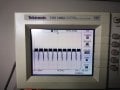
I use a 5khz wave and 15 Khz carrier (Y1). I am just getting a scrambled waveform. Nothing resembling a modulation.
Has anyone worked with this IC before with AM modulation and been successful ?


Ken
 

OBW0549

Joined Mar 2, 2015
3,566
It should work, datasheet says is DC to 250Mhz
Yes, it should work-- if you use it properly.

I get good signals on the leads, but the output of the AD835 is awful.
The output is awful because your modulation frequency and your carrier frequency are too close together. With only a 3:1 difference between them, you cannot expect anything but a total mess out of the AD835.

Try 150 Hz and 15 kHz instead, and see what it looks like.
 

crutschow

Joined Mar 14, 2008
34,280
The first is with a 15kHz carrier and a 500Hz modulation frequency.
The second is with a 15kHz carrier and 5Khz modulation frequency.
See what everyone has been trying to tell you?

1592963873467.png 1592963957646.png
 

Thread Starter

captoro

Joined Jun 21, 2009
207
Yes, it should work-- if you use it properly.


The output is awful because your modulation frequency and your carrier frequency are too close together. With only a 3:1 difference between them, you cannot expect anything but a total mess out of the AD835.

Try 150 Hz and 15 kHz instead, and see what it looks like.
I tried that , does not work, Used 1mhz as carrier and 7 khz as wave modulated. Its still a mess.
Added a 0.1 cap on the input, seems to have improved but not by much.

Ken
 

Thread Starter

captoro

Joined Jun 21, 2009
207
You have not shown your supply voltage, or your carrier and modulation levels and waveshapes. Then we can simulate it since you don't.
I am using a power supply to get +/- 9 volts, then a LM7805 and 7905 to get the desired voltage. Three cature of the same wave shape at different time.
 

Attachments

Audioguru again

Joined Oct 21, 2019
6,671
Again you do not say your carrier and modulation frequencies, levels and waveshapes. If they are 1MHz and 7kHz sinewaves then it is impossible for the output to be that squared 4kHz low level signal shown in your 1st photo.

Your breadboard is a mess of wires all over the place with nothing labelled. It looks like you are coupling the carrier and modulation signals with series capacitors that block the important 0VDC needed by the inputs.
 

Thread Starter

captoro

Joined Jun 21, 2009
207
Again you do not say your carrier and modulation frequencies, levels and waveshapes. If they are 1MHz and 7kHz sinewaves then it is impossible for the output to be that squared 4kHz low level signal shown in your 1st photo.

Your breadboard is a mess of wires all over the place with nothing labelled. It looks like you are coupling the carrier and modulation signals with series capacitors that block the important 0VDC needed by the inputs.
I am using the circuit for am modulation in the datasheet. I modified the frequency. Still not getting the expected waveform.
 

Attachments

Thread Starter

captoro

Joined Jun 21, 2009
207
I am using the circuit for am modulation in the datasheet. I modified the frequency. Still not getting the expected waveform.
Carrier is at 4mhz and the waveform is at 24khz.
Seems that the 24khz is not affecting the output at all
 

Thread Starter

captoro

Joined Jun 21, 2009
207
Your 'scope is set to see the carrier frequency that is bouncing up and down at the lower frequency modulation frequency.
Instead, set your 'scope to show a few cycles of the modulation frequency.
Ok. Works when I reduced the cycles. Thanks. I did manage to burn one of the IC though.
 
Top