alternator wrongly labelled

Thread Starter

stratford4528

Joined Nov 8, 2018
8
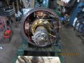
I bought a very old alternator with the original label on it. It said 440 volts 3 phase. I connected it to a suitable engine and tried to get it to produce 440 volt. It would only produce 220 volts. after many attempts and reading some paperwork I came to a conclusion it was 220 volt 3 phase. It had been wrongly labeled on leaving the factory. Because it is in as new condition I want to reconnect the coils to 440 volts 3 phase. It has 12 coils on the rotor and 4 slip rings with the 4 field coils bolted to the case. On disconnecting the joints on the coils it appears that each coil produces 110 volts and 4 coils were connected in parallel. I want to connect 4 coils in series and parallel to give me 220 volts.Can any one help with a wiring sketch as I cannot find any information any where.
Thank you Bob
 

MisterBill2

Joined Jan 23, 2018
18,502
Before you disconnect anything you need to mark the start and finish of each winding. If there are presently four windings in parallel for each phase then the marking needs to include both start and which phase each wire for each winding is.Otherwise you will have 12 wires with 144 possible combinations of which 142 of them will be wrong. So good secure marking is important. If you are lucky, all of the wires may already be marked, in which case you need to carefully record how they are connected.
To get 440 volts from the 4 110 volt windings they need to have all four in series additive, and for three phase with 440 between phases they all need to be tied in a delta configuration. So it is indeed complicated. I recommend trying to find information from the original manufacturer.
One thing that you will find is that the power will be about the same but the current will be one quarter as much. Is there any connection information on the nameplate? And what company manufactured the alternator?
 

Thread Starter

stratford4528

Joined Nov 8, 2018
8
Unfortunately there is no information available. As I said the original name plate is wrongly labeled. The alternator was made by ecc back in the seventies. I did mark the windings and reconnected as I thought correct. but it did not work out. The other problem is there was no AVR so had to work out which suitable. It would have had a transformer regulator. I was hoping to see a sketch of how to connect the coils. I think 1,4,7,10 have to be connected as one phase but which way I cannot work it out.. I have a little experience in generators because I completely designed and built my own wind turbine alternator.
 

MisterBill2

Joined Jan 23, 2018
18,502
OK, and so it may take a bit of experimentation to get everything working correctly. Regulation is always a challenge because it is a feedback circuit and so not only gain but response time are important for stability. Fortunately there are a number of automatic voltage regulators available that hopefully have those issues worked out. Putting 4 windings in series with the correct phasing will be a bit of a challenge, although if you are able to spin the alternator with a crank it may make experimenting more convenient. The fact of four slip rings is a bit of a puzzle indeed. You mention 4 field windings bolted to the housing and twelve windings on the rotor, which that sounds like it would be connected for star rather than delta. How difficult is it to change the winding connections on the rotor? That is something that I have not seen. But since you have mentioned 4 windings in parallel I am presuming that it is possible without a lot of effort to change them. And if all four slip rings are connected then it must be a "WYE" connection and not a delta. So working out the correct connections just got a lot simpler.. Also, for a nominal 440 volts between phases, each phase to neutral will be about 277 volts. So now your big challenge will be finding which is the start and which is the finish , and splitting the arrangement into a 2 by 2 string for each set. It would seem that in the previous arrangement one slip ring had connections from all of the coils while the other tthree slip rings had only connections from 4 coils. Please let us know if that was the case.
 

Thread Starter

stratford4528

Joined Nov 8, 2018
8
OK, and so it may take a bit of experimentation to get everything working correctly. Regulation is always a challenge because it is a feedback circuit and so not only gain but response time are important for stability. Fortunately there are a number of automatic voltage regulators available that hopefully have those issues worked out. Putting 4 windings in series with the correct phasing will be a bit of a challenge, although if you are able to spin the alternator with a crank it may make experimenting more convenient. The fact of four slip rings is a bit of a puzzle indeed. You mention 4 field windings bolted to the housing and twelve windings on the rotor, which that sounds like it would be connected for star rather than delta. How difficult is it to change the winding connections on the rotor? That is something that I have not seen. But since you have mentioned 4 windings in parallel I am presuming that it is possible without a lot of effort to change them. And if all four slip rings are connected then it must be a "WYE" connection and not a delta. So working out the correct connections just got a lot simpler.. Also, for a nominal 440 volts between phases, each phase to neutral will be about 277 volts. So now your big challenge will be finding which is the start and which is the finish , and splitting the arrangement into a 2 by 2 string for each set. It would seem that in the previous arrangement one slip ring had connections from all of the coils while the other tthree slip rings had only connections from 4 coils. Please let us know if that was the case.
Moderators note : removed excesive quotes
 
Last edited by a moderator:

Thread Starter

stratford4528

Joined Nov 8, 2018
8
440 volt phase to phase
I am having problems replying. I managed to connect 4 windings in series which as I numbered them 1 4 7 10. I left the other windings disconnected and pushed them in to the end of the rotor and secured them with cable ties. I tested it and had nearly 200 volts. I adjusted the AVR and got 230 volts. So I thought I could now connect the other windings 2 5 8 11 and 3 6 9 12 But it all went wrong some of the coils burnt out but not the ones I had connected. So Its back to the drawing board. I have stripped it out and picking up wire on Monday to rewind it
 

MisterBill2

Joined Jan 23, 2018
18,502
I am having problems replying. I managed to connect 4 windings in series which as I numbered them 1 4 7 10. I left the other windings disconnected and pushed them in to the end of the rotor and secured them with cable ties. I tested it and had nearly 200 volts. I adjusted the AVR and got 230 volts. So I thought I could now connect the other windings 2 5 8 11 and 3 6 9 12 But it all went wrong some of the coils burnt out but not the ones I had connected. So Its back to the drawing board. I have stripped it out and picking up wire on Monday to rewind it
My guess is that the windings that burned were tied together , but start to finish and so they had reversed polarities, resulting in an effective short circuit. for parallel connection what you need is start to start and finish to finish, assuming that they are wound in the same direction. If you are able to disconnect the alternator from the engine and crank it by hand it should be possible to see if a set of windings is connected correctly without risking damage if they are not. Then a 120 volt light bulb from each phase to the common slip ring should flash in succession as the armature is rotated with the crank.. Polarity in alternator windings is very important.
 

Thread Starter

stratford4528

Joined Nov 8, 2018
8
My guess is that the windings that burned were tied together , but start to finish and so they had reversed polarities, resulting in an effective short circuit. for parallel connection what you need is start to start and finish to finish, assuming that they are wound in the same direction. If you are able to disconnect the alternator from the engine and crank it by hand it should be possible to see if a set of windings is connected correctly without risking damage if they are not. Then a 120 volt light bulb from each phase to the common slip ring should flash in succession as the armature is rotated with the crank.. Polarity in alternator windings is very important.
None of the windings were connected to each other. What must have happened 2 ends must have come together when I pushed them inside. It was one coil that was badly burnt.
What I worked out is the start of coil 1 goes to the slip ring. The end of coil1 is connected to the end of coil 4. The start of coil 4 is connected to start of coil 7. The end of coil 7 is connected to the end of coil 10. The start of coil 10 goes to slip ring. Being 4 pole 1 and 7 is the same polarity and 4 and 10 are the same polarity That is how I got it to work the last time I tested it. Do you agree. It has been doing my head in. I am glad I don't have to count my time because I am retired. But I need this genny to replace a very old Perkins with a Leyroy Sumners alternator which I will sell.
I would like to thank you for your help. Would you mind telling me where you are based. I'm in South Wales
Regards Bob
 

Attachments

MisterBill2

Joined Jan 23, 2018
18,502
None of the windings were connected to each other. What must have happened 2 ends must have come together when I pushed them inside. It was one coil that was badly burnt.
What I worked out is the start of coil 1 goes to the slip ring. The end of coil1 is connected to the end of coil 4. The start of coil 4 is connected to start of coil 7. The end of coil 7 is connected to the end of coil 10. The start of coil 10 goes to slip ring. Being 4 pole 1 and 7 is the same polarity and 4 and 10 are the same polarity That is how I got it to work the last time I tested it. Do you agree. It has been doing my head in. I am glad I don't have to count my time because I am retired. But I need this genny to replace a very old Perkins with a Leyroy Sumners alternator which I will sell.
I would like to thank you for your help. Would you mind telling me where you are based. I'm in South Wales
Regards Bob
OK, Bob, I see that the whole system is complex and also heavy. I am located in the city or Royal Oak, state of Michigan, USA, quite a distance away, about 7 hours by air.
I can see why the whole project is taking a lot of effort, and I am wondering just a bit why 440 volts 3-phase power? I am aware that the UK runs 220 volts, but what is used in South Wales is unknown to me. And while power through the slip rings is certainly one way to create 3 phase, I would choose to have a rotating field and put the power windings on the stator, so that the current through slip rings would be much less. Perhaps on the next generator you purchase?
 

Thread Starter

stratford4528

Joined Nov 8, 2018
8
OK, Bob, I see that the whole system is complex and also heavy. I am located in the city or Royal Oak, state of Michigan, USA, quite a distance away, about 7 hours by air.
I can see why the whole project is taking a lot of effort, and I am wondering just a bit why 440 volts 3-phase power? I am aware that the UK runs 220 volts, but what is used in South Wales is unknown to me. And while power through the slip rings is certainly one way to create 3 phase, I would choose to have a rotating field and put the power windings on the stator, so that the current through slip rings would be much less. Perhaps on the next generator you purchase?
The alternator is very well made and had very little use. At £50 it was cheap. The lister engine has only done 600 hrs and cost me £70. I buy items from time to time, store them and eventually make a unit up. I have other alternators and engines which I will do the same. It has always been a hobby of mine. Possibly because as a child I grew up with out electricity and tap water. I am self taught in every thing I do. If the alternator had been 440 volt like the label said I would not have the problems. In fact it would have been ideal for your country because it was also 60Hzs. I have slowed it down to 50Hzs which we are over here. I know all modern alternators have rotating fields. In the UK all 3 phase is 440 volts. Because I am 100% off grid I need a three phase genny to run a big motor. When I eventually get it running it will be an Ideal replacement. Also I can start it by hand so I won't need to leave batteries on it if I don't use it for a few weeks. I had no choice when I bought it I could not refuse a bargain as I thought. Some of the gennys I do are the old Lister CS engines if you know them. The engine runs at 650 RPM. When They first came out they were a 2.5 KVA startamatic. When you switched a light on they would start when you switched the last item they stopped. I can send you a photo if you want
 

MisterBill2

Joined Jan 23, 2018
18,502
The alternator is very well made and had very little use. At £50 it was cheap. The lister engine has only done 600 hrs and cost me £70. I buy items from time to time, store them and eventually make a unit up. I have other alternators and engines which I will do the same. It has always been a hobby of mine. Possibly because as a child I grew up with out electricity and tap water. I am self taught in every thing I do. If the alternator had been 440 volt like the label said I would not have the problems. In fact it would have been ideal for your country because it was also 60Hzs. I have slowed it down to 50Hzs which we are over here. I know all modern alternators have rotating fields. In the UK all 3 phase is 440 volts. Because I am 100% off grid I need a three phase genny to run a big motor. When I eventually get it running it will be an Ideal replacement. Also I can start it by hand so I won't need to leave batteries on it if I don't use it for a few weeks. I had no choice when I bought it I could not refuse a bargain as I thought. Some of the gennys I do are the old Lister CS engines if you know them. The engine runs at 650 RPM. When They first came out they were a 2.5 KVA startamatic. When you switched a light on they would start when you switched the last item they stopped. I can send you a photo if you want
Very interesting indeed. and I am aware of the compulsion when I see a great deal. I just purchased a slightly used 5500 watt generator system a few weeks ago. It is triple fueled, gasoline, LP gas, or home heating gas. My challenge to getting that one going is running the 1 inch gas line 65 feet from the outside meter, underground to where the generator will be, on the back side of the house. Gas pipe installation is not a task that I enjoy.
 
Top