Facebook
 Google
 GitHub
 Linkedin


Hello! it's been some time since my initial post about a solenoid driver circuit. I finished it up recently, and with a couple of small ammendment things were working great. Or so I thought.
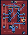
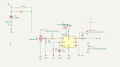
To explain, the purpose of this circuit is to drive a solenoid in a plastic gun shell, like the Arcade games Point Blank and Time Crisis. There is a sensor in the shell along with a solenoid, exactly like the original arcade guns. This one though, routes to a Playstation 2 Guncon 2 PCB. The sensor circuit is wired into the guncon board, and then my tiny solenoid driver PCB is also wired in for GND, 5v and the trigger drives the timing on the TLC555.
Now, the issue at hand is, that while it works, with the 24v supply to the solenoid turned on, it starts missing shots and the aim goes skewiff. It's semi-playable, but it's much less accurate than it is with the solenoid deactivated.
I have a TVS diode across the coil, close to the solenoid, the guncon and solenoid boards are about 6ft of wire away.
What I think is happening is that because the guncon board is sharing the ground with the other two devices, the voltage spike is upsetting it. So my proposed next step is to try using an optocoupler to read the trigger from the board and keep it electronically isolated. the only downside is, I'm going to have to shell out a load for 100 pieces from RS plus postage, and I couldn't find any cheap ones on ebay (although I haven't looked for many different ones) so I wanted to a) be sure this is a sane idea, and b) ask if there was anything else to try first.
Any advice?