Facebook
 Google
 GitHub
 Linkedin
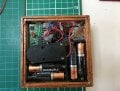
The voltages are rather low for a nominally 6V supply. Are the batteries a respectable brand and fresh?
Those vibrations suggest the receiver isn't getting a high enough voltage and is switching off.
Are you sure the receiver is putting out a continuous signal when the button is kept pressed?
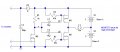
Re-running a simulation of the circuit I find that the pulse when the button is pressed or released is particularly sensitive to the Vgs threshold of the FETs. Datasheets indicate your chosen FETs can have a threshold as high as +-2V, which simulation shows is too high to give a reliable pulse. However, if the circuit was working ok at one stage, the implication is that the thresholds of the particular FET samples you actually have are closer to +-1V, which is good.
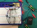
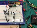
A clear breadboard pic might be informative.
Those vibrations suggest the receiver isn't getting a high enough voltage and is switching off.
Are you sure the receiver is putting out a continuous signal when the button is kept pressed?
Re-running a simulation of the circuit I find that the pulse when the button is pressed or released is particularly sensitive to the Vgs threshold of the FETs. Datasheets indicate your chosen FETs can have a threshold as high as +-2V, which simulation shows is too high to give a reliable pulse. However, if the circuit was working ok at one stage, the implication is that the thresholds of the particular FET samples you actually have are closer to +-1V, which is good.
A clear breadboard pic might be informative.
Last edited: