Advice on power supply for circuit

Thread Starter

NickB

Joined Feb 1, 2016
95
Hi

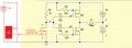
A while ago a couple of chaps on here were kind enough to help me create a dual polarity pulser circuit. The circuit is powered by 4 x AAA batteries split into two banks of 3v (see schema), the circuit works great.

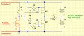
The circuit is activated by an RF remote (momentary type). However, I’m having to use a separate 6v power supply for the receiver (common ground) but I’d prefer to use just one power supply if possible. I’ve tried adding a diode and capacitor (as in the second schema) and whilst the coil will pull a magnet towards it, it won’t reverse and repel it as intended.

Anyone have any thoughts on how I could achieve this using a single power source? Any input greatly appreciated.

Cheers
Nick
 

Attachments

crutschow

Joined Mar 14, 2008
38,503
What is the frequency/waveshape/voltage of the signal from the receiver?
How is the signal from the receiver different between pulsing M1 and pulsing M2?
 

Thread Starter

NickB

Joined Feb 1, 2016
95
Hi Crutschow, thanks for the input.

I'm a bit of a novice so I'll try and answer as best I can

The signal voltage from the receiver is the same as its supply - 6v. When using schema 2 I get one pulse when the button on the remote is pressed but no reverse pulse when the button is released (unlike schema 1, where I get a reverse pulse when the button is released).

Thanks
Nick
 

crutschow

Joined Mar 14, 2008
38,503
When using schema 2 I get one pulse when the button on the remote is pressed but no reverse pulse when the button is released (unlike schema 1
So you are saying the addition of the diode and capacitor changed the operation of the circuit?
I don't understand that. :confused:
 

Thread Starter

NickB

Joined Feb 1, 2016
95
Bear in mind that in schema 2 I'm trying to use a single power source (the two banks of AAA batteries) plus the addition of the diode and capacitor. In schema 1 I'm using an additional 6v supply to power the receiver. Hope that makes sense.
 

ebeowulf17

Joined Aug 12, 2014
3,307
Appreciate that. Please see updated schema 1 below.

The power source for the receiver uses two CR2032 batteries as space is very limited in this project.

Thanks
Nick
Could you pull your 6V receiver voltage from the same 4 batteries that provide +/-3V elsewhere, and ignore the common ground requirement, by using an opto isolator between the receiver output and the rest of the circuit?

I haven't thought this all the way through... I have a hunch that this could be done with a small opto and 2-3 extra resistors, but l could be way off. Just brainstorming, and it's past my bedtime!
 

crutschow

Joined Mar 14, 2008
38,503
Based upon your two schematics, I don't see why the circuit won't work when you are powering the receiver off the same batteries as the solenoid driver uses. :confused:
 

Thread Starter

NickB

Joined Feb 1, 2016
95
Based upon your two schematics, I don't see why the circuit won't work when you are powering the receiver off the same batteries as the solenoid driver uses. :confused:
Neither do I but it only half works.

I'm not using a solenoid, just a tiny (home made - approx 100 winds of 32swg copper wire on a 5mm air core), coil to attract and repel a magnet. When using schematic 2 in my OP the coil attracts the magnet when the receiver is activated, but won't repel the magnet afterwards like the circuit is intended to do. It does when using an additional power supply though.

Cheers
Nick
 

Thread Starter

NickB

Joined Feb 1, 2016
95
Could you pull your 6V receiver voltage from the same 4 batteries that provide +/-3V elsewhere, and ignore the common ground requirement, by using an opto isolator between the receiver output and the rest of the circuit?

I haven't thought this all the way through... I have a hunch that this could be done with a small opto and 2-3 extra resistors, but l could be way off. Just brainstorming, and it's past my bedtime!
Using an opto coupler - that's a thought. Not sure what this would look like but may be worth further investigation.

Cheers
Nick
 

ebeowulf17

Joined Aug 12, 2014
3,307
Looking at this with fresh eyes this morning, I'm with @crutschow. I don't see any good reason why separate supplies should be needed, nor the diode/cap arrangement, nor my earlier opto suggestion.

If I'm reading this circuit right, the critical requirement for getting your pulses to work is for the node where MOSFET drain and 1k resistor meet to change voltages quickly enough. Apparently this is working fine when the receiver gets a signal and outputs a high (6V) signal, activating the MOSFET, but when it comes to turning the MOSFET off, it's happening too slowly to generate the pulse.

One thought I had was that the batteries simply didn't have enough juice, and that separating the loads meant less remaining work for your AAA batteries to do, but I have to say it doesn't quite make sense if I try to picture how that failure plays out.

Another possibility is that the MOSFET gate ends up floating or holding a residual charge which takes time to dissipate, so the MOSFET turns off slowly instead of quickly. Again, I can't see how separate vs. shared batteries would effect this, but I'm just trying to work my way backwards from the missing pulse.

Despite not having a clear explanation for why battery arrangements would change this, I still find myself gravitating towards a gate charge question. Perhaps a pull-down resistor (10k, maybe a little lower?) from MOSFET gate to ground could be added to insure that when it turns off, it really turns off right away. Without knowing the internal architecture of your receiver, I don't know if its output is push/pull, open collector, etc. I don't have a high degree of confidence in this suggestion, but it should be a pretty safe, harmless experiment, so maybe it's worth a shot.
 

Thread Starter

NickB

Joined Feb 1, 2016
95
Looking at this with fresh eyes this morning, I'm with @crutschow. I don't see any good reason why separate supplies should be needed, nor the diode/cap arrangement, nor my earlier opto suggestion.

If I'm reading this circuit right, the critical requirement for getting your pulses to work is for the node where MOSFET drain and 1k resistor meet to change voltages quickly enough. Apparently this is working fine when the receiver gets a signal and outputs a high (6V) signal, activating the MOSFET, but when it comes to turning the MOSFET off, it's happening too slowly to generate the pulse.

One thought I had was that the batteries simply didn't have enough juice, and that separating the loads meant less remaining work for your AAA batteries to do, but I have to say it doesn't quite make sense if I try to picture how that failure plays out.

Another possibility is that the MOSFET gate ends up floating or holding a residual charge which takes time to dissipate, so the MOSFET turns off slowly instead of quickly. Again, I can't see how separate vs. shared batteries would effect this, but I'm just trying to work my way backwards from the missing pulse.

Despite not having a clear explanation for why battery arrangements would change this, I still find myself gravitating towards a gate charge question. Perhaps a pull-down resistor (10k, maybe a little lower?) from MOSFET gate to ground could be added to insure that when it turns off, it really turns off right away. Without knowing the internal architecture of your receiver, I don't know if its output is push/pull, open collector, etc. I don't have a high degree of confidence in this suggestion, but it should be a pretty safe, harmless experiment, so maybe it's worth a shot.
Hi Ebowulf17, many thanks for the suggestion. I'll try a pull down this evening and report back.

Once again many thanks for your input.

Regards
Nick
 

Thread Starter

NickB

Joined Feb 1, 2016
95
Looking at this with fresh eyes this morning, I'm with @crutschow. I don't see any good reason why separate supplies should be needed, nor the diode/cap arrangement, nor my earlier opto suggestion.

If I'm reading this circuit right, the critical requirement for getting your pulses to work is for the node where MOSFET drain and 1k resistor meet to change voltages quickly enough. Apparently this is working fine when the receiver gets a signal and outputs a high (6V) signal, activating the MOSFET, but when it comes to turning the MOSFET off, it's happening too slowly to generate the pulse.

One thought I had was that the batteries simply didn't have enough juice, and that separating the loads meant less remaining work for your AAA batteries to do, but I have to say it doesn't quite make sense if I try to picture how that failure plays out.

Another possibility is that the MOSFET gate ends up floating or holding a residual charge which takes time to dissipate, so the MOSFET turns off slowly instead of quickly. Again, I can't see how separate vs. shared batteries would effect this, but I'm just trying to work my way backwards from the missing pulse.

Despite not having a clear explanation for why battery arrangements would change this, I still find myself gravitating towards a gate charge question. Perhaps a pull-down resistor (10k, maybe a little lower?) from MOSFET gate to ground could be added to insure that when it turns off, it really turns off right away. Without knowing the internal architecture of your receiver, I don't know if its output is push/pull, open collector, etc. I don't have a high degree of confidence in this suggestion, but it should be a pretty safe, harmless experiment, so maybe it's worth a shot.
Just tried a 10k pull down between the gate and ground. Same result unfortunately. Also tried brand new Duracells to make sure there's sufficient power.

Any other suggestions welcome.

Cheers
Nick
 

ebeowulf17

Joined Aug 12, 2014
3,307
Just tried a 10k pull down between the gate and ground. Same result unfortunately. Also tried brand new Duracells to make sure there's sufficient power.

Any other suggestions welcome.

Cheers
Nick
Sorry, I've got nothing. I'll be following this thread with great interest to see how it turns out. You're in good hands with crutschow and AnalogKid here.
 

Thread Starter

NickB

Joined Feb 1, 2016
95
Sorry, I've got nothing. I'll be following this thread with great interest to see how it turns out. You're in good hands with crutschow and AnalogKid here.
You guys are all superheros on here! It fries my brain this stuff but I'm keen to learn.
 

AnalogKid

Joined Aug 1, 2013
12,126
Which is the intent of the circuit,

a:
coil current left to right
off time
coil current right to left
off time
repeat

or b:
coil current left to right
coil current right to left
repeat

?

ak
 
Top