Facebook
 Google
 GitHub
 Linkedin
Hi everyone,
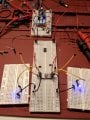
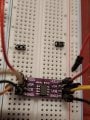
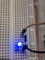
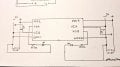
I am new to building electronics and working with microcontrollers, very new. I am working on a project where I want to isolate signals from my controllers (pi and Arduino). Before this, I made the mistake of cooking both controllers with one misplaced wire. Since then, I bought some new controllers, optocouplers, and magnetic Isolators on amazon to create full isolation for new controllers. I got the optocouplers working fine, BUT, I for the life of me cannot get the Adum 1201 to work... I may be going about it wrong. I wanted to simulate sending a signal with a breadboard set up before actually hooking it up, now here is the problem, when I powered each side of board with its own power (3.3v) the signal (VIA, VOB, VOA, VIB) pins have a voltage. I've tried a lot of configurations and can't seem to figure out how to get them to operate. I thought that they would work as optocouplers do, signal in, signal out, however the pins already have a voltage, I was thinking that these pins need to be at 0v so that when I send a non gpio signal from controller to device, they turn on. Like I said, the only way I could get them to simulate a transfer was by disconnecting the ground of its pair across the magnetic bridge. I've looked at the sheets, searched youtube, asked GPT to no avail. Please help me community. Please ask for clarifications.
I am new to building electronics and working with microcontrollers, very new. I am working on a project where I want to isolate signals from my controllers (pi and Arduino). Before this, I made the mistake of cooking both controllers with one misplaced wire. Since then, I bought some new controllers, optocouplers, and magnetic Isolators on amazon to create full isolation for new controllers. I got the optocouplers working fine, BUT, I for the life of me cannot get the Adum 1201 to work... I may be going about it wrong. I wanted to simulate sending a signal with a breadboard set up before actually hooking it up, now here is the problem, when I powered each side of board with its own power (3.3v) the signal (VIA, VOB, VOA, VIB) pins have a voltage. I've tried a lot of configurations and can't seem to figure out how to get them to operate. I thought that they would work as optocouplers do, signal in, signal out, however the pins already have a voltage, I was thinking that these pins need to be at 0v so that when I send a non gpio signal from controller to device, they turn on. Like I said, the only way I could get them to simulate a transfer was by disconnecting the ground of its pair across the magnetic bridge. I've looked at the sheets, searched youtube, asked GPT to no avail. Please help me community. Please ask for clarifications.