
 Facebook
 Google
 GitHub
 Linkedin

Hi!
I will be using Arduino to control a h-bridge like this:
h-bridge: Yet another MOSFET based h-bridge

Without any protection, the wiring is easy:

But I don't want to leave it like this, I want to be on the safe side and add some safety, primarily for the MCU.
First, I would like to ask for some suggestions for type of protection, if I know that PWM wont exceed 31 kHz and A and B wont change faster than once in a few tens of milliseconds.
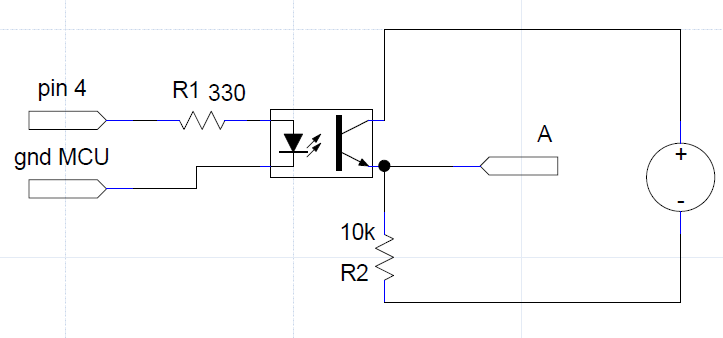
One thing I found to protect my MCU was optocoupler. But I bumped against a problem when I tried using it. That problem was that A and B can change their roles, being low at one time or high at other. That means electricity has to flow in both directions. Optocoupler cant do that, so I would probably have to add a pulldown resistor somewhere. But, here I become concerned that this will affect the amount of current coming to the BJTs. If this happens, it might change the way author predicted this circuit to work. The BJTs might not get saturated enough, causing too small current to flow to the FETs and thus charging the gate capacitors too slow. It might be just me being paranoid though, but I already burned one of these h-bridges on 31 kHz, so I had to lower the resistors leading to FET gates to 1k.
For example: when that A acts as high, the current goes from it to ground, but it has to pass through that 10k resistor. But since it already passed through one 10k resistor that is part of h-bridge design, the current diminishes more than it should have. On the other hand I need that 10k resistor there for the case when A acts as low.
Please help!
I will be using Arduino to control a h-bridge like this:
h-bridge: Yet another MOSFET based h-bridge
Without any protection, the wiring is easy:
But I don't want to leave it like this, I want to be on the safe side and add some safety, primarily for the MCU.
First, I would like to ask for some suggestions for type of protection, if I know that PWM wont exceed 31 kHz and A and B wont change faster than once in a few tens of milliseconds.
One thing I found to protect my MCU was optocoupler. But I bumped against a problem when I tried using it. That problem was that A and B can change their roles, being low at one time or high at other. That means electricity has to flow in both directions. Optocoupler cant do that, so I would probably have to add a pulldown resistor somewhere. But, here I become concerned that this will affect the amount of current coming to the BJTs. If this happens, it might change the way author predicted this circuit to work. The BJTs might not get saturated enough, causing too small current to flow to the FETs and thus charging the gate capacitors too slow. It might be just me being paranoid though, but I already burned one of these h-bridges on 31 kHz, so I had to lower the resistors leading to FET gates to 1k.
For example: when that A acts as high, the current goes from it to ground, but it has to pass through that 10k resistor. But since it already passed through one 10k resistor that is part of h-bridge design, the current diminishes more than it should have. On the other hand I need that 10k resistor there for the case when A acts as low.
Please help!
Last edited:






