 Facebook
 Google
 GitHub
 Linkedin
Ciao, it's Pablo! First of all, thanks for reading:
So I'm stuck in a project for my university. I was designing a very simple ElectroMyoGraph circuit -which I'll show you below- and works just fine. However I'm trying to add a new phase to amplify the signal read on my oscilloscope (just in case) so that it may be adjusted if needed. My idea is to use a potentiometer so that I can manually vary the resistance of a new phase of the circuit (not implemented in the drawing below) and change the gaining as needed.
First I thought of substituting both buffers or voltage followers (which you can see on the left, which is where the electrodes coming from the biceps are connected to) by an instrumental amplifier yet it proved unfruitful (don't know why but the output remained unaltered). So then I tried a simple non-inverting amplifier at the end and it worked somewhat rarely, maybe the voltage overcome the 9V maximum... Not sure.
I would appreciate any light you can shed (suggestions, warnings, constraints, ...) or any other idea you might want to share with me (maybe a new, more productive circuit phase). Thank you a lot.
DATA:
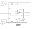
The original circuit is a Differential Amplifier. It has two buffers connected to it at the beginning, connected in turn to the biceps electrodes. V3 is the output that leads to the oscilloscope for signal reading:
Right now the gain of the differential amplifier is 500KOhms (R1=R3=800KOhms and R2=R4=400KOhms). The voltage supply for the LF353 OpAmps is 9V (I'm guessing I can't obtain a signal higher than that, just correct me if I'm wrong).
The non-inverting amplifier had a gain between 1 and 3V: Rf = 0-40KOhms and R1 = 20KOhms
So I'm stuck in a project for my university. I was designing a very simple ElectroMyoGraph circuit -which I'll show you below- and works just fine. However I'm trying to add a new phase to amplify the signal read on my oscilloscope (just in case) so that it may be adjusted if needed. My idea is to use a potentiometer so that I can manually vary the resistance of a new phase of the circuit (not implemented in the drawing below) and change the gaining as needed.
First I thought of substituting both buffers or voltage followers (which you can see on the left, which is where the electrodes coming from the biceps are connected to) by an instrumental amplifier yet it proved unfruitful (don't know why but the output remained unaltered). So then I tried a simple non-inverting amplifier at the end and it worked somewhat rarely, maybe the voltage overcome the 9V maximum... Not sure.
I would appreciate any light you can shed (suggestions, warnings, constraints, ...) or any other idea you might want to share with me (maybe a new, more productive circuit phase). Thank you a lot.
DATA:
The original circuit is a Differential Amplifier. It has two buffers connected to it at the beginning, connected in turn to the biceps electrodes. V3 is the output that leads to the oscilloscope for signal reading:
Right now the gain of the differential amplifier is 500KOhms (R1=R3=800KOhms and R2=R4=400KOhms). The voltage supply for the LF353 OpAmps is 9V (I'm guessing I can't obtain a signal higher than that, just correct me if I'm wrong).
The non-inverting amplifier had a gain between 1 and 3V: Rf = 0-40KOhms and R1 = 20KOhms
Attachments
-
 43 KB Views: 11
 -
 43 KB Views: 9


