Add a work light to powertools (Powered Screwdriver)

Thread Starter

JoeCK

Joined Mar 20, 2020
62
Hi All,

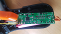
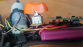
I would like to integrate a work light on my powered screwdriver.
I have added to LED (3mm) bulbs to my tiny cute IKEA screwdriver on two sides of the body of the screwdriver towards the tip. The battery powering the tool is one 3.7v 16850.

The wiring I did was simple, (maybe wrong?)
Just wire the LEDs to the motor terminals in forward and reverse polarity, so they start to light up as the motor gets the forward/reverse polarity power switching.

However, the problem is only one of the LEDs is surviving after a few minutes of use. That dying/dimming LED is mostly forward driving one ( I tried replacing the LEDs 3 times). Is there any back emf or something acting here?

How do I implement this successfully, please?

Kind Regards
 

Attachments

Thread Starter

JoeCK

Joined Mar 20, 2020
62
Did you put a 100 ohms resistor in series with the led,?
Hi again mate,

I did not! Shall I try by adding one and inline with (+) or (-) for both the LEDs, please?
Will you kind enough to let me know the purpose of the resistor in series)

Any specific reason for using 100Ω? (I have 4.7Ω, 3.3Ω, 30Ω, 47Ω, 20Ω, 1Ω all 0.25W 1% ready in my hand)

Thank you
 

djsfantasi

Joined Apr 11, 2010
9,156
Yes, there is a particular for 100Ω.

LEDs require current control. They have two parameters which you usually need in order to power and LED.

The first parameter is forward voltage. This is the voltage drop the LED has in typical operation.

The second parameter is current required to drive the LED. If this current becomes too large, the LED will fail. Typical currents are 20mA, but they operate well with a current as low as 5mA. You really need to understand (the datasheet) each LED you use.

This is the equation used to calculate the resistance:
R = (Vs - Vf) / I(led!​
Vs is the supply (battery) voltage. Vf is the forward voltage and I(led) is the LED current.

100Ω is a typical resistance that works in many cases.
 

Thread Starter

JoeCK

Joined Mar 20, 2020
62
To keep the current under 20mA so they won't burn out. 3.7V/100Ω = 37mA / 2leds = 18.5mA each.
Hi Guys,

Thank you for the quick reply.

Can I use any of these (by combining) 4.7Ω, 3.3Ω, 30Ω, 47Ω, 20Ω, 1Ω (all 0.25W 1%) since these are ready to hand pls? If so what are the values and series/parallel?
 

Thread Starter

JoeCK

Joined Mar 20, 2020
62
Hi, Will it work safely one bulb in forward and one bulb in reverse motor spinning, if resistors connected like in the image pls?
Also, resistors can be on any lead right? (just updated image)
powertool-worklight.jpg
And thank you for your reply.
 

Attachments

Last edited:

SamR

Joined Mar 19, 2019
5,031
It needs to be in series, either on the + or - leg, not both. Or you would need 200Ω for EACH LED individually. I = V/R so it needs to be under 20mA to keep the LED current in spec. If only one LED at a time, it needs 200Ω.
 

Thread Starter

JoeCK

Joined Mar 20, 2020
62
If only one LED at a time, it needs 200Ω.
Yes, only one LED will be lite at a time (while screwing or unscrewing)

So, should I be using 200Ω?

Any chance I can see a rough drawing of the resistor connection to LEDs pls?

If I could request;
Is it possible to use both LEDs while screwing/unscrewing? (in the screwdriver, motor power simply reversing battery polarity to achieve clockwise and anti clockwise rotations)
 

Thread Starter

JoeCK

Joined Mar 20, 2020
62
Well there is possible and then there is feasible. Without looking at the schematic or if there is physical space I can't answer.
There seems to be small place inside... (maybe for small components)
Do we need any additional circuit board to achieve this? Or can be done by diodes?

I will send the photos while it's opened.
 

SamR

Joined Mar 19, 2019
5,031
Without looking at the schematic or if there is physical space I can't answer.

I assume like most it has a reverse switch. I don't know where you are getting your input power but assume it is somehow related to the trigger. Too many unknowns. IF there is some way to power the LEDs from the trigger and not have the polarity reversed they yes, you could power both at once. It may be possible to do some tricks with diodes, see above. YMMV
 

djsfantasi

Joined Apr 11, 2010
9,156
Since it is low current, a small DIP rectifier could be used (or a sm. round rectifier, like in the second link). Maybe.

Use of a bridge rectifier to convert the motor power to DC for the LEDs, will have about 1.4 V lost in the diodes. With a 3.7V battery, that only leaves 2.3V for the LED and current control resistor.

That may not be enough.

https://www.mouser.com/Semiconducto...tifiers/Bridge-Rectifiers/_/N-ax1mf?P=1z0yye2

https://m.aliexpress.com/item/32627...zUI77Le0JqZIeloFlmhoCNA8QAvD_BwE&gclsrc=aw.ds
 

SamR

Joined Mar 19, 2019
5,031
Good point, I didn't take into account the V drop across any additional diodes. Doesn't leave any meat on the bone with only a 3.7V supply...
 
Last edited:

djsfantasi

Joined Apr 11, 2010
9,156
If you could find a 3P On-Off-On switch that could replace the existing switch either directly or with minor mounting changes, you could make this work.

Two poles would be wired as a reversing switch. The common terminals would go to the motor. One outside pair of contacts would connect to the two battery terminals and then you would wire the outside contacts in a crossover configuration.

The third pole would switch power to the LEDs. The common would go to one battery terminal. The outside contacts would be wired together and then to the appropriate LED connection. The other battery connection goes to the LEDs (or the resistors).
 

Thread Starter

JoeCK

Joined Mar 20, 2020
62
Hello Guys,

I have changed the LEDs and added 200Ω in series all seem to work fine so far :)

Also Interested to know how to make both the LEDs work in both clockwise and anti-clockwise directions.

Please find the attached images of the inside PCB and 3pole switch (Trigger to the bottom to run to clockwise and trigger the top run to the anti-clockwise direction.

Kind Regards,
 

Attachments

Top