ADC using volTage DivideR

Thread Starter

karunadas@hotmail.com

Joined May 2, 2013
6
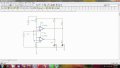
I made an circuit in breadboard as done in the picture like in the attachment. Well I also made an trial circuit on TINA PRO software and when I do simulation than I get problem.

Well the results should be like for __________ Vin Binary output

-------------->> LED 1 LED 2

For 0v --> off off
For 1v -- > on off
For 2v --> off on
for 3v --> on on

My Vref is 12 volt. Well on doing the practical everythng works fine till 0v and 1v. but after i give Vin as 2 volts, both led glows instead of one glowing and other off. Please help and tell me where I am wrong.
 

Attachments

Last edited:

JoeJester

Joined Apr 26, 2005
4,390
I made an circuit in breadboard as done in the picture like in the attachment. Well I also made an trial circuit on TINA PRO software and when I do simulation than I get problem.
Your telling me the breadboard worked as you desired and the simulation didn't?
 

WBahn

Joined Mar 31, 2012
33,204
Are you sure that the non-inverting input of both opamps is supposed to be tied to the positive rail?

How, given this circuit, is the output of an opamp supposed to change from one state to the other and then change back as the input voltage is increased?
 

WBahn

Joined Mar 31, 2012
33,204
You say it should work but you won't answer my question of how it is supposed to change from one state to another and then back. Can you explain WHY you think that LED1, after going on at 1V, should go back off at 2V?
 

Thread Starter

karunadas@hotmail.com

Joined May 2, 2013
6
yes I had replaced the power input of both pin 4 and 7 by another source of +- 5V. Still it does not works... can u please make me understand the circuit...?? I am very amateur
 

WBahn

Joined Mar 31, 2012
33,204
yes I had replaced the power input of both pin 4 and 7 by another source of +- 5V. Still it does not works... can u please make me understand the circuit...?? I am very amateur
Could you please post an updated schematic so that we can see what you are working with?

Also, please tell us very clearly what your PHYSICAL circuit is doing and, separately from that, what your SIMULATED circuit is doing.
 

WBahn

Joined Mar 31, 2012
33,204
actually that was what I was thnkng..but my supervisor kept on telling that itz d circuit
Please stop the text speak, it is not appreciated here.

And please try to write in complete thoughts. I have know idea what "that" was that you were thinking or which circuit "itz" is refering to.

You need to learn to communicate clearly and precisely if you ever hope to get anywhere in engineering. Consider this a really good opportunity to practice.
 

WBahn

Joined Mar 31, 2012
33,204
Can anyone of you please provide me a CIRCUIT DIAGRAM of 2 BIT ADC using op-amps??
Uhmmm.... Did you READ the Lab Handout that you posted? The whole point of the lab is for you to learn about the 3-bit ADC that they walk you through and give you all of the circuit diagrams for. You should be able to modify that to cut it down to a 2-bit if you so desire.

Don't just ask for us to give you the solutions to your homework. You need to show an honest effort and ask specific questions that are causing you trouble.
 
Top