 Facebook
 Google
 GitHub
 Linkedin
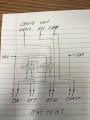
The cruise control turns on when it sees +12v but my steering wheel only has momentary switches so I need to do this. Since these switches are just rubber like in a remote control, I don’t think they can handle the current a normal relay draws - or at least not for very long - so I want to go solid state. Then I was thinking - is there already an IC that does what I’m trying to do here?
Basically one switch turns on a NO relay which then powers itself to stay closed. The second switch turns off a NC relay which disconnects power to the first relay. This allows me to have two momentary switches perform the duty of a toggle switch. You can ignore the COAST and ACCEL wiring.
Basically one switch turns on a NO relay which then powers itself to stay closed. The second switch turns off a NC relay which disconnects power to the first relay. This allows me to have two momentary switches perform the duty of a toggle switch. You can ignore the COAST and ACCEL wiring.
Attachments
-
 155.5 KB Views: 12


