 Facebook
 Google
 GitHub
 Linkedin
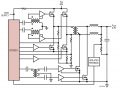
Preface: I have a need for a 250-500 VDC input, 48-65 VDC output DC-DC for converter. Right now, it is in the "building one section at a time" stage of power board. I inquired here previously, being rather vague as I'm working on a custom design and I don't want to disclose too much before I've figured it out. Someone here suggested that I try the LTC1922 phase shifted full bridge controller chip. Using the reference design in the datasheet, outlined basically in the first pic, I was able to actually get it working. I have an isolated FET drive I use on any serious H-bridge I build. I very confident in this drive scheme. Right now I have a working board that is mostly identical to the reference design, except I use +12 V, -5 V isolated gate drive voltages for all four quadrants, through a NPN/PNP buffer for each. A TLP250 drives each quadrant from the LTC1922 chip. It works great.
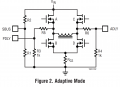
HOWEVER!!: The reference design is powered from primary voltage and the secondary is isolated. I want to opposite. I want the 48 V side to be the logic power, but the 450 V side to be the isolated primary. This means ground references have to swap and that means that the ZVS sensing feedback is on the isolated primary side. I need to isolate the SBUS, ADLY, and PDLY and transfer that info across the isolation barrier. The LTC1922 senses the bus voltage at SBUS and the voltage at the S-D junction of each half bridge with ADLY and PDLY illustrated in the 2nd picture.
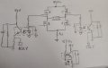
The SBUS expects to see around 1.5 V when the primary bus voltage is nominal. And then determines when to switch based on the voltage at each half bridge. Could it be as simple as pic 3, with optocouplers like I've shown?
HOWEVER!!: The reference design is powered from primary voltage and the secondary is isolated. I want to opposite. I want the 48 V side to be the logic power, but the 450 V side to be the isolated primary. This means ground references have to swap and that means that the ZVS sensing feedback is on the isolated primary side. I need to isolate the SBUS, ADLY, and PDLY and transfer that info across the isolation barrier. The LTC1922 senses the bus voltage at SBUS and the voltage at the S-D junction of each half bridge with ADLY and PDLY illustrated in the 2nd picture.
The SBUS expects to see around 1.5 V when the primary bus voltage is nominal. And then determines when to switch based on the voltage at each half bridge. Could it be as simple as pic 3, with optocouplers like I've shown?
Attachments
-
 89.2 KB Views: 12
 -
 81.7 KB Views: 11
 -
 1.4 MB Views: 10


