Actuator with timer and switch

Thread Starter

jonnydolt

Joined Oct 23, 2015
145
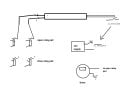
Hi guy's I could use a little assistance to work out some 12 v dc wiring .I wish to have a timer to extend an actuator and then a switch to manually retract the actuator.The usage is for a roosters night box.At night I need to be able to flick a switch to extend the actuator to open the door ,then place the bird inside and then flick the switch to close it .In the morning I need the timer to give power to the actuator to extend and open the door automatically so the bird can get out and then at a later time I need to be able to flick a switch and manually retract the actuator and close the door .Many thanks in advance.. List of some of the bits and bobs I have ... ..http://www.ebay.com.au/itm/161552313910?_trksid=p2057872.m2749.l2649&ssPageName=STRK:MEBIDX:IT ...... http://www.ebay.com.au/itm/112009092626?_trksid=p2057872.m2749.l2649&var=410949586181&ssPageName=STRK:MEBIDX:IT .... http://www.ebay.com.au/itm/221759451485?_trksid=p2057872.m2749.l2649&ssPageName=STRK:MEBIDX:IT ....... http://www.ebay.com.au/itm/Car-20A-...877603?hash=item33caed3de3:g:~gAAAOSwV0RXso5z Edit the actuator has built in limit switch's but I would have to use external ones as I cannot position the actuator properly
 

drc_567

Joined Dec 29, 2008
1,156
What is your source of DC power? ... a car battery?

Can you provide some kind of sketch showing the different components and what they are supposed to do?
 

Thread Starter

jonnydolt

Joined Oct 23, 2015
145
rooster box 001.jpg
What is your source of DC power? ... a car battery?

Can you provide some kind of sketch showing the different components and what they are supposed to do?
Timer is to give power to the actuator at 8.am .Another switch will be needed to manually retract the actuator when I get down to the pen ,the switch will be needed at night to turn on the actuator to reopen the box and then again to close the box after the rooster is inserted.I used 12 volt gear as I have a solar panel etc that I will set up for it at a later date
 

Thread Starter

jonnydolt

Joined Oct 23, 2015
145
Both box's together .The actuator needs to go on the outside as it is all glued and screwed together.Originally I had gas struts and an auto lock but the lock will not work when pressurised so I was forced to rethink and use an actuator
 

Attachments

Thread Starter

jonnydolt

Joined Oct 23, 2015
145
The actuator does have built in limit switch's however,I cannot find a happy medium point to mount it so I will need to mount an external limit switch
 

drc_567

Joined Dec 29, 2008
1,156
A limit switch will just go in-line to one of the power cords of the actuator. It will open when the actuator rod reaches the position where it is placed. When it opens, the actuator will stop.

The next problem is to get the actuator to reverse and close the door. To do this, it will be necessary to change the DC polarity of the leads going to the actuator.

It looks like it is going to be necessary to use a relay to control the polarity of the leads going to the actuator .. that is to get it to open and close.

... Have to figure a way to make the relays work in the correct sequence ... One time open, then next time close.
 

Tonyr1084

Joined Sep 24, 2015
7,905
Peanut Gallery approach:

Buy a commercially available timer and set it to the time you want. The one I like is a digital timer that can be set in one minute increments. In your case, at 8:00 AM the timer would switch on and off at 8:01 AM. During that minute a relay can act as a push button switch to open the door. A limit switch would shut power to the switch when the door reaches the full open position. Then, any time you like you can push a manually operated button to open or close the door as you like.

I did something similar with my garage door opener. Sometimes we forget to close the door. Having the system set up so that at various times (up to 20 programmable times) if the door is in the open position a relay can activate and close the door. Of course, this involves the garage door opener, which you don't need. Just a relay and a limit switch to open the door at the prescribed hour and minute.

Here's a rough draft of what I did:

At 7:30 AM the timer turns on for one minute. IF the garage door is open then the microswitch completes a circuit actuating a 120 VAC relay. The contacts of the relay act like the wall switch and the door begins to close. As soon as the door leaves the microswitch the relay drops out but the door still closes because all it needed was a signal to close. IF the door is NOT open at 7:30 AM then no relay signal is sent and the door does NOT open. Not unless someone opens it manually. Reverse of what you want, but the concept is pretty straight forward.

[edit] I should mention the timer is plugged into the wall.

Garage Door Closer.png
 
Last edited:

drc_567

Joined Dec 29, 2008
1,156
Here is a preliminary sketch of the basic idea. A pair of relays, both actuated at the same time will polarize the actuator so that it will open. When a normally closed limit switch is hit, the current from the 12v supply will be interrupted and the door will cease motion. The relay pair can be actuated from the timer or a manual push button switch.
In order to close the door, the break in DC supply current will have to be manually overided for a moment to get the 'close relay pair' to start working and retract the door ...manually.

note: the close relay pair is wired so that the polarization of the actuator is reversed. Only one relay pair is actuated at one time.

One or two details to take care of ...

Does the idea make sense?
 

Attachments

Last edited:

drc_567

Joined Dec 29, 2008
1,156
When you close the door by pressing a button switch to activate the close relay pair, are you able to stop the return motion manually, or is it necessary to install a limit switch at the door closed position?
 

Thread Starter

jonnydolt

Joined Oct 23, 2015
145
I have managed to mount the actuator so it opens and closes using the actuators internal limit switches ,so my thinking is if I use the timer and a relay I could have the timer open the door at 8am and then close at 8.30am,then I could wire 1 switch after the relay so I can manually open the door and wire another switch to manually close the door after the rooster is put in.If I am correct having the 2 switches wired after the relay should override the timer If this is so the conundrum now is that I have a switch giving power to retract the actuator and then at 8am the timer will also give power but to extend the actuator .Would an On off On switch solve this problem
 
Last edited:

drc_567

Joined Dec 29, 2008
1,156
I need the pin-out description of th 8 pin relay you are using... and also maybe the switch you are using.

Suggested Circuit Description:
... One way to get this to work and be able to operate the actuator in both open and close directions is to have two separate sets of single pole relays.

One of the relay pairs wires the + and - supply voltage to the actuator so that the door opens. ... both of those particular relay coils are wired so that the 8am timer signal turns them on together. Then, when the door is opened and the far limit switch is reached, the supply voltage to those relay coils is turned off ... just opening the + wire connection is sufficient to do this, which is what the far limit switch is for.

The other design goal is to allow the actuator to close the door using a push button switch at the box. To do this, the + and - wiring from the power supply must go to the actuator terminals in such a manner that it is reversed from the previous wiring. By using an additional pair of single pole relays, activated both at once, by a switch at the box, with the + and - relay output reversed from the previous arrangement, everything will work as intended.

So, if you run into any difficulties, like maybe the timer output pulse is not long enough, or too long, or whatever, just post a description of what is going on, and it can probably be fixed.
 
Top