AC Solenoid current calculation

Thread Starter

brianmk

Joined Dec 23, 2016
59
Hi Brian,
Reading through your posts, may I ask why it is so important that you know the exact solenoid current?

E
The current calculation doesn't need to be exact. I was just interested to discover why my calculation differed from the measured result.

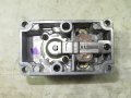
My aim was to try and match the failed solenoid coil (for both resistance and inductance).
One of my concerns was that the coil gets quite hot when energised.
Eventually the coil will be re-encapsulated in potting compound (for mechanical stability and gas safety reasons).
If the current in my replacement home-wound coil turns out to be higher than the original then the operating temperature will be higher. That would increase the probability of failure.
I originally thought that encapsulating the solenoid in potting compound would exacerbate the temperature issue.
However I have subsequently read that because potting compound conducts heat better than air, it should actually help dissipate the heat.

Today I measured the true rms current in the replacement gas valve solenoid. It measured 250mA.
That's exactly the same as my home-wound solenoid so I am now reasonably confident that I have the right number of turns on the coil and that the resistance matches the original. That means the coil temperature should be about the same.
 

MisterBill2

Joined Jan 23, 2018
19,630
The shading lop in the photo is much more massive than any I have seen in a comparable size solenoid. Vastly larger, in fact.
In addition, it crosses a much greater volume of the magnetic field.
 

MisterBill2

Joined Jan 23, 2018
19,630
To assure the desired penetration of the potting compound it should have a low viscosity when the coil is immersed in it, and, very important, the assembly should be held in a vacuum for a bit to pull the air out from the winding, so that the potting can penetrate all of the voids in the winding.. That is why some electromagnetic coils are immersed in insulating varnish and vacuum impregnated.. It also greatly improves the mechanical integrity of the winding.
 

Thread Starter

brianmk

Joined Dec 23, 2016
59
To assure the desired penetration of the potting compound it should have a low viscosity when the coil is immersed in it, and, very important, the assembly should be held in a vacuum for a bit to pull the air out from the winding, so that the potting can penetrate all of the voids in the winding.. That is why some electromagnetic coils are immersed in insulating varnish and vacuum impregnated.. It also greatly improves the mechanical integrity of the winding.
When I pulled the failed solenoid apart, only the outer 2/3 layers of the winding had potting compound glued to them. That makes me think no vacuum was used when it was originally potted.
When winding my coil I applied varnish every two layers to help with the mechanical integrity and make it easier to keep adjacent turns close together. The original coil had no varnish.
I will probably warm the potting compound before pouring it to make it less viscous - although I have read that you get an exothermic reaction when mixing the hardener in any case.
 

MrAl

Joined Jun 17, 2014
11,770
By connecting a scope across a small series resistor I was able to monitor the current waveform.
It looks more like a triangular wave than a sine wave. See attached photo.

That may explain why the current measured using an AVO is not as expected.
An AVO full-wave rectifies an AC signal and the moving coil meter responds to the average.
A calibration factor is applied to the scale to display the rms value assuming a sine wave.
The calibration factor for a sine wave is 0.707/0.633 = 1.11
For a triangular wave it would need to be 0.577/0.5 = 1.15

That means that the true rms value is actually higher than indicated on the AVO.
i.e. 228mA rather than 220mA.

I verified this by measuring the current with a true rms DMM.
The DMM measures 250mA - presumably because it's not a perfect triangular wave.

A triangular waveform means that calculating the current becomes a lot more complicated.
I imagine it would involve Fourier analysis and summing the harmonics?

I have attached a photo of the rewound solenoid that shows the shading loop.
Hi,

Yes the "calibration factor" is often called a "crest factor".

You do not need Fourier to calculate the RMS current you just do an integration.
RMS stands for "root of the mean of the square" and can be calculated as follows.
First square the waveform, then take the mean, then take the square root.
For a regular sawtooth triangle, the wave is:
y=A*t/T
where
A is the amplitude, t is time, and T is the period.
So, we first square that and get:
A^2*t^2/T^2
now we calculate the mean by first using an integration over the period T:
integrate(A^2*t^2/T^2,t,0,T) and get:
A^2*T/3
then divide by T to finish the calculation of the mean and get:
A^2/3
then finally take the square root and get:
A/sqrt(3)
so the RMS value is:
yrms=A/sqrt(3)
which is the peak amplitude divided by the square root of 3.

This was for a sawtooth triangle, but because a more symmetrical triangle has to sides exactly the same as a sawtooth that means we have twice the area but also twice the width, which means the RMS value comes out to the same value:
Yrms=PeakAmplitude/sqrt(3)

Now if the triangle goes positive and negative it does not matter because when we square it the entire wave ends up being positive.

If the triangle has rounded peaks, then we have to modify the original wave before we square it. That could mean doing a piecewise calculation using discrete points on the wave, or approximating the wave with two waves. One could be a partial triangle and the other a partial sine wave near the peaks for example. We would do the same thing though just with two different waves instead of just one.
 

Thread Starter

brianmk

Joined Dec 23, 2016
59
An excellent explanation.

One thing that bothers me though...
Without carrying out actual measurements, how would I figure out the peak amplitude of the pseudo-triangular waveform based upon coil resistance, inductance and the applied AC sinewave voltage?
As the voltage/current relationship appears to be non-linear (sine wave voltage in, triangular current out), can LTspice be used in this situation?
 
Last edited:

MaxHeadRoom

Joined Jul 18, 2013
28,856
The shading lop in the photo is much more massive than any I have seen in a comparable size solenoid. Vastly larger, in fact.
In addition, it crosses a much greater volume of the magnetic field.
Personally I do not see any shading ring? it has to encircle the whole coil or solenoid at some point. , the whole idea is to create a phase shift in that part of the coil in order for the elimination of 'buzz' from the armature when the sine wave crosses zero.
 
Last edited:

Thread Starter

brianmk

Joined Dec 23, 2016
59
Personally I do not see any shading ring? it has to encircle the whole coil at some point. , the whole idea is to create a phase shift in that part of the coil in order for the elimination of 'buzz' from the armature when the sine wave crosses zero.
I agree that the idea is to avoid 'buzz'.
As I understand it, the copper ring behaves rather like a shorted turn in a transformer secondary.
It creates a magnetic field during the period when the magnetic field created by the primary would otherwise be zero.
Other forum experts may be able to help out here.
 

MaxHeadRoom

Joined Jul 18, 2013
28,856
Yes, as I stated, it has to perform a perfect loop or conductor around or in parallel to the main field, the idea is to create a phase shifted magnetic field as the main field crosses zero point.
 

Thread Starter

brianmk

Joined Dec 23, 2016
59
This is why I became an engineer.
You start with something as apparently simple as a coil of wire wound on a magnetic core and you generate all these questions.
 

MaxHeadRoom

Joined Jul 18, 2013
28,856
One reason that DC solenoids became popular and started to replace the AC version , it has been rather slower here in N.A. than in Europe, where they have been more popular for many more decades.
When I would spec them in to custom machinery here , I would get push-back from the CO's engineering dept's, "We have always done it this way" !!
 

Thread Starter

brianmk

Joined Dec 23, 2016
59
Yes, as I stated, it has to perform a perfect loop or conductor around or in parallel to the main field, the idea is to create a phase shifted magnetic field as the main field crosses zero point.
The initial photo of the coil I gave does not show the moveable armature that activates the gas valve.
When the solenoid is installed in the valve and is active, the armature creates a closed magnetic loop.

I am not trying to come up with an improved solenoid design here.
All I am trying to do is repair a failed solenoid in an obsolete gas valve.
As a retired engineer with a pitiful pension I am unable to afford a new boiler!
 
Last edited:

Alec_t

Joined Sep 17, 2013
14,430
As the voltage/current relationship appears to be non-linear (sine wave voltage in, triangular current out), can LTspice be used in this situation?
The LTspice sim I posted (#20) doesn't show triangular current; just slight distortion of sinusoidal. So the modelling obviously isn't correct.
 

MaxHeadRoom

Joined Jul 18, 2013
28,856
The main armature is not the phase shifted conductor, as in other devices that have an armature, e.g. a large contactors, you have the main armature and a secondary coil(s) placed. at a different point in the field.
 

Thread Starter

brianmk

Joined Dec 23, 2016
59
The main armature is not the phase shifted conductor, as in other devices that have an armature, e.g. a large contactors, you have the main armature and a secondary coil(s) placed. at a different point in the field.
You know what? I don't give a , as long as the boiler works and I can feel warm!
 
Last edited by a moderator:

MisterBill2

Joined Jan 23, 2018
19,630
OK, Max does not see the single turn shading coil because it is not what he is looking for. If that is the same coil as the original had, then OK, go for it. The TS now knows exactly how to replace the valve operating coil. And has already done what I would have suggested! So go for it, Brian! Just be careful to not let the potting material gum up the works by getting on that lever that operates the valve.
And be sure that the lid seal is gas tight!!
 

MrAl

Joined Jun 17, 2014
11,770
An excellent explanation.

One thing that bothers me though...
Without carrying out actual measurements, how would I figure out the peak amplitude of the pseudo-triangular waveform based upon coil resistance, inductance and the applied AC sinewave voltage?
As the voltage/current relationship appears to be non-linear (sine wave voltage in, triangular current out), can LTspice be used in this situation?
Hi,

It's kind of difficult to calculate that because you have to use some special math and you also have to know, beforehand, the characteristics of the core material, which is kind of difficult in itself if you do not know who made the laminations.

In a simulation, the coil has to be made from a nonlinear model, which would include some parameters which you would either have to measure (ha) or get from the manufacturer of the laminations. It has to be nonlinear because a linear model would show a perfect sine response.
There is a good chance we could come up with a behavioral model, which would give us a similar waveform, but I wonder how much good it would do. In cases like this it is good to do that when you want to study the general effects but to get the specific response you need to know a lot about the construction.

This means we either measure the response or ask the manufacturer of the coil to provide more information, which they may not have either.

As I was saying, if we have a decent picture of the waveform we can calculate the RMS value from that and get pretty close, but that does require a measurement.

There are a few old sayings. One is, "One measurement is worth a thousand expert opinions".
There is more to it than that though as sometimes it's the other way around, but that applies to a lot of stuff I think.
This is because sometimes there are a lot of parameters to consider in order to get a decent result from a calculation.
 

MrAl

Joined Jun 17, 2014
11,770
This is why I became an engineer.
You start with something as apparently simple as a coil of wire wound on a magnetic core and you generate all these questions.
A wise old engineer told me a very long time ago that a coil of wire has properties that link to the entire universe through the magnetic field. In classical theory, the field goes out to infinity, and that means if there is an edge to the universe it goes out that far. How long it takes would of course depend on the speed of light. It's kind of interesting to picture that field and how big it would be. The field strength would be much smaller way out there, but not zero, given enough time, but often it is viewed as instantaneous even though it couldn't really be so.

If you really care to dig into the theory of inductors, look up the Jiles-Atherton model. It's kind of complicated though.
 

MaxHeadRoom

Joined Jul 18, 2013
28,856
OK, Max does not see the single turn shading coil because it is not what he is looking for
What is that supposed to mean?? :rolleyes:
A shading ring should be in the same plane as the main coil.
In a relay for e.g. it is usually a single ring on top of the main coil.
Never at right angles to the main coil.

Relay e.g. (red arrow indicates it)
1704153988769.png
 
Top