Facebook
 Google
 GitHub
 Linkedin
This should be simple, but...
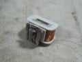
I have a 24V 50Hz AC solenoid.
The DC resistance of the coil measures 70 Ohms at ambient temperature.
The solenoid has a U shaped iron core with a moveable armature.
When energised, the core and armature form a closed magnetic circuit.
The core includes a copper shading ring.
I measured the inductance with the armature closed using a Marconi bridge.
If I measure using the internal 1kHz oscillator I get 180mH.
If I use an external low frequency oscillator in the region of 50Hz, I get 440mH.
I assume the difference is due to the permeability of the iron core changing with frequency?
I want to calculate the expected rms current when the solenoid is connected to a 24V 50Hz AC supply.
Using the 440mH figure, the reactance of the coil at 50Hz is 138 Ohms.
That gives a total impedance of 155 Ohms, phase angle 63deg.
Hence I would expect the current to be 24 / 155 = 155mA rms.
When I hook up a test circuit I actually measure around 220mA rms (using an AVO which approximates rms).
The current drops to about 200mA as the coil warms up.
I don't understand why the measured current differs from the calculated result.
What have I overlooked?
Is it because the shading ring distorts the current waveform?
If it's no longer a true sine wave then the current as measured on an analogue moving coil ammeter won't be accurate.
Last edited: