Facebook
 Google
 GitHub
 Linkedin
Audioguru again
- Joined Oct 21, 2019
- 6,826
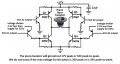
If you add an inductor parallel with the piezo as a DC load for the transistor then it will play only one loud frequency since the inductor and the capacitance of the piezo make a tuned LC circuit. If a high power resistor is used as a DC load then the squeaker can play a few high pitched frequencies.
The horn of the squeaker concentrates its few high frequencies in one direction.
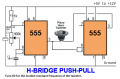
The maximum voltage of the piezo horn squeaker is +35V and -35V which is 70V peak-to-peak. Then it can be driven from a push-pull audio amplifier powered from +37V and -37V which would produce 153 real Watts into 4 ohms or 77 real watts into 8 ohms. Driven with 70V peak-to-peak the piezo squeaker will produce a few loud high-pitched frequencies.
The horn of the squeaker concentrates its few high frequencies in one direction.
The maximum voltage of the piezo horn squeaker is +35V and -35V which is 70V peak-to-peak. Then it can be driven from a push-pull audio amplifier powered from +37V and -37V which would produce 153 real Watts into 4 ohms or 77 real watts into 8 ohms. Driven with 70V peak-to-peak the piezo squeaker will produce a few loud high-pitched frequencies.