 Facebook
 Google
 GitHub
 Linkedin
Hello everyone!
After I've introduced myself in Community subforum, I decided to ask for a help over here, although, I will also ask for forgiveness if I misplaced this thread or did anything else that is against the rules (I've read the Rules though") ).
).
So, the thing is, I have a few electronic parts laying around that I've mostly salvaged from old computers, power amplifiers etc.
I am trying to build myself a decent variable power supply, single channel will do with outputs of around 30-40V, current limiting feature and it should be able to provide at least 5A. USB power connector would be also great and since I ordered a Arduino with a LCD display shield, I might even go and integrate a voltage-current meter. If not, I'll just go and buy that Red-Blue meter that you can buy online for a few dollars...
Now, I do realize that in most cases it might be smarter if not even cheaper to go ahead and buy myself a PSU from store, however, as I am quite new to electronics and this would be my first real project from which I hope to learn something as well as have a nice product in the end, I would really appreciate if you would go easy on me with this one.
So, first things first.
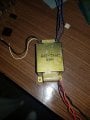
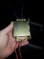
I want to design and create my first part of this PS, a circuit that will provide DC voltage. Now, I have a transformer whose photo I will attach here that is taking 220VAC on primary (I live in Croatia, Europe) and spits out 60VAC on one secondary with center tap (so I can have 30VAC here as well) and 32VAC on the other secondary also with a center tap (16VAC available here). Since the transformer has no markings whatsoever besides 641-788C and 15Q0ZP on itself, I got these data by connecting it to my mains and measuring voltage on secondaries.
Now, I really don't put too much hope that someone here will be able to tell me if this transformer will be capable of delivering 6-7 amps or not, but I will say that it is a quite heavy transformer, 1,94 kilograms to be more precise (4,27 pounds) and since I really can't say by anything else, I'll just have to believe it will be good enough for its purpose in this project. Of course, I'm open to any argument if someone thinks it won't be.
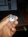
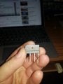
Second thing here is a Full Bridge Rectifier. I have two rectifiers that I'm really not 100% sure what are their capabilities. As I mentioned, I'm quite a newbie here so I would really appreciate if someone could point me to datasheet and actually what data should I be looking for there. I do know it should be able to take at least 10-20% more Voltage than the Transformer is going to feed it with, it should be able to take at least 6-7 of amps of current (if I'm not wrong) and it shouldn't dissipate too much heat.
So, rectifiers that I have are:
S5VB 60 63 (number 3 at the end has a horizontal line above it as you can see on the photo)
D3SBA20
Anyway, thank you very much for taking time to at least read this huge post, and even more if you bother yourself with replying.
PS
Sorry for my bad english
After I've introduced myself in Community subforum, I decided to ask for a help over here, although, I will also ask for forgiveness if I misplaced this thread or did anything else that is against the rules (I've read the Rules though
).So, the thing is, I have a few electronic parts laying around that I've mostly salvaged from old computers, power amplifiers etc.
I am trying to build myself a decent variable power supply, single channel will do with outputs of around 30-40V, current limiting feature and it should be able to provide at least 5A. USB power connector would be also great and since I ordered a Arduino with a LCD display shield, I might even go and integrate a voltage-current meter. If not, I'll just go and buy that Red-Blue meter that you can buy online for a few dollars...
Now, I do realize that in most cases it might be smarter if not even cheaper to go ahead and buy myself a PSU from store, however, as I am quite new to electronics and this would be my first real project from which I hope to learn something as well as have a nice product in the end, I would really appreciate if you would go easy on me with this one.
So, first things first.
I want to design and create my first part of this PS, a circuit that will provide DC voltage. Now, I have a transformer whose photo I will attach here that is taking 220VAC on primary (I live in Croatia, Europe) and spits out 60VAC on one secondary with center tap (so I can have 30VAC here as well) and 32VAC on the other secondary also with a center tap (16VAC available here). Since the transformer has no markings whatsoever besides 641-788C and 15Q0ZP on itself, I got these data by connecting it to my mains and measuring voltage on secondaries.
Now, I really don't put too much hope that someone here will be able to tell me if this transformer will be capable of delivering 6-7 amps or not, but I will say that it is a quite heavy transformer, 1,94 kilograms to be more precise (4,27 pounds) and since I really can't say by anything else, I'll just have to believe it will be good enough for its purpose in this project. Of course, I'm open to any argument if someone thinks it won't be.
Second thing here is a Full Bridge Rectifier. I have two rectifiers that I'm really not 100% sure what are their capabilities. As I mentioned, I'm quite a newbie here so I would really appreciate if someone could point me to datasheet and actually what data should I be looking for there. I do know it should be able to take at least 10-20% more Voltage than the Transformer is going to feed it with, it should be able to take at least 6-7 of amps of current (if I'm not wrong) and it shouldn't dissipate too much heat.
So, rectifiers that I have are:
S5VB 60 63 (number 3 at the end has a horizontal line above it as you can see on the photo)
D3SBA20
Anyway, thank you very much for taking time to at least read this huge post, and even more if you bother yourself with replying.
PS
Sorry for my bad english
Attachments
-
 111.2 KB Views: 27
 -
 106.9 KB Views: 27
 -
 198.9 KB Views: 26
 -
 118.5 KB Views: 28


