About Stepper Motors

Thread Starter

q12x

Joined Sep 25, 2015
2,227
And Jony130's circuit is right for the bottom section, I don't know why I re-edited it to the wrong version the way I did.
Should I re re-edit it, do you think?
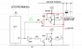
Always edit the mistakes !!! I learn it the hard and slow way. BECAUSE you will forget. Not today, not tomorrow but definitely after 1week of hundreds of permutations. At least in my case. As 'hard' as it looks and feels now, it will be good in the long run. You can trust me on this. I spent a good amount of time on editing cct images or simulation circuits. Its a pain in the buuut is the right thing. And the right thing is paying off very slowly and on the long run. It adds up. So be consistent, be tenacious, be disciplined. Be like q12 !
 

Thread Starter

q12x

Joined Sep 25, 2015
2,227
to @sarahMCML - I built your circuit and is not working.
I power it up to 12V.
I got signal before the 4k7 but after it, in the red marked square, absolutly no pulse, nowhere. The motor is not powered-not spinning.
1666787915526.png 20221026_151023.jpg 20221026_151028.jpg
(It would be nice to be able to arrange the images more freely here in the post. mmmmmm)
 
Last edited:

BobTPH

Joined Jun 5, 2013
11,523
You really need to learn about high side drivers if you insist on using NPN or N-channel MOSFETs on the high side. What you have will not work. You need a power supply that is 10V higher than your motor power supply to drive a high side MOSFET, or an isolated supply referenced to the source. There are high side driver chips that use a capacitor bootstrap circuit to achieve this, but they work only if the circuit is switching constantly, which is no good for a stepper motor driver.

Far simpler is to use PNP or P-channel MOSFETs on the high side. Every bridge driver I have made does that.
 

Thread Starter

q12x

Joined Sep 25, 2015
2,227
... if you insist on using NPN or N-channel MOSFETs on the high side.
We are trying our best. I did tried my best with NPN's and it kind of worked. My friend here, @sarahMCML is trying her best with mosfets. I believe she got it working in her side. But I didnt in mine. Tings are evolving. Dont say hop yet.
The thing is I dont insist. I dont have what I need. Yet. But is on its way. After I will get it we will do it the proper way. I believe it is possible to make it only with N-ch as well. We olny need the right recipe. If we will not get it, at least we tried.
This is what we are doing here. Put your ideas on the table here. Correct any mistakes. Bring new insights. The more, the better.
 

BobTPH

Joined Jun 5, 2013
11,523
I’m sorry, but you are getting bad advice. The high side driver circuit cannot work. In fact, the problem was never the way the gate was driven, the problem was using the wrong transistors.

It is so much simpler to use PNP, but that seems to be the one thing you won’t try. The reason people use N-MOSFETs on the high side is that it is hard to find P-channel ones that are good for high power - tens of Amps, but you are not doing that.
 

ericgibbs

Joined Jan 29, 2010
21,444
hi Q,
This is your completed circuit.
E

NOTE: It is NOT connected to suit a Stepper, it is just to show the operation of your MOSFET driver circuit working.


EG57_ 153.png
 
Last edited:

Thread Starter

q12x

Joined Sep 25, 2015
2,227
My friend mister @Jony130
I tried your much simple circuit. Is --kind-- of working...
I can hear the motor doing some noise but not spinning.
I had the inspiration to lower the Amperage and the Voltage from my PSU before testing anything!!!! Probably everything would had exploded to the ceiling. Nothing bad happened. But this is what happened: I lowered the voltage to ~3V and the Amp to ~500mA. I raised slowly the A and V, one by one, until I reach 4.7V- 5V BUT with A at 1.2A - Ohoa. At this level, the motor started to make some quiet bump noises but not really spinning. I could hear it at lower V or A but at higher sound pitch and very quiet (not changing the fv from the 555).
Another bad aspect. The Top Mosfets, some of them, not all, like 2, got Very Hot, and 1 was Excessively Hot and I could smell it as very hot metal. Hmmmm.... I don't think a heat sink will do any real difference.
I know we have to reach over 10V !!! I know. I could not reach that voltage because 1.2A at 5V. Haha.
Another interesting observation:
The Heat sink the voltage regulator LM317 for 5V maintained cool at room temperature ! With this circuit. Comparative to ALL other BJT cct's before, he was raising considerably in heat level !!! So that's good news, that nothing is surging mysteriously like before.
My idea to continue this cct we have on the table right now :
- I believe we need a Variable Current Regulator for the Motor AND the Mosfet cct. 1or2 of them. Im not very familiar with these types of cct's. Except current limiting with a resistor or with a PWM... but at much lower power V/A. I believe I only used PWM on variation of voltage but not on current. Or perhaps it did both in the same time.... Meh...
Thank you so far. This is progress !
----
Thank you for the proteus circuit !
I modified it slightly to fit my way of building on the breadboard. Is working fine in simulation.
4wire v4 - N-ch Mosfets - Jony130 - v2.jpg
Also I attach the modified save file as well:
 

Attachments

Last edited:

shortbus

Joined Sep 30, 2009
10,050
Are these 4 wire motors your working with? They are "bipolar motors if they are. Trying to use a unipolar drive scheme will not work.

I have a proven schematic from an old magazine that many people used to run a 4 wire motor if you want I scan it and post it. But be aware no micro controller is used in it.
 

Thread Starter

q12x

Joined Sep 25, 2015
2,227
Are these 4 wire motors your working with? They are "bipolar motors if they are. Trying to use a unipolar drive scheme will not work.
I have a proven schematic from an old magazine that many people used to run a 4 wire motor if you want I scan it and post it. But be aware no micro controller is used in it.
Yes they are 4wire stepper motors. Yes I want your circuit. Dont ask, just put it in. Be independent ! Haha.
The logic part of the cct is no problem whatsoever.
 

BobTPH

Joined Jun 5, 2013
11,523
My friend mister @Jony130
I tried your much simple circuit. Is --kind-- of working...
I can hear the motor doing some noise but not spinning.
I had the inspiration to lower the Amperage and the Voltage from my PSU before testing anything!!!! Probably everything would had exploded to the ceiling. Nothing bad happened. But this is what happened: I lowered the voltage to ~3V and the Amp to ~500mA. I raised slowly the A and V, one by one, until I reach 4.7V- 5V BUT with A at 1.2A - Ohoa. At this level, the motor started to make some quiet bump noises but not really spinning. I could hear it at lower V or A but at higher sound pitch and very quiet (not changing the fv from the 555).
Another bad aspect. The Top Mosfets, some of them, not all, like 2, got Very Hot, and 1 was Excessively Hot and I could smell it as very hot metal. Hmmmm.... I don't think a heat sink will do any real difference.
I know we have to reach over 10V !!! I know. I could not reach that voltage because 1.2A at 5V. Haha.
Another interesting observation:
The Heat sink the voltage regulator LM317 for 5V maintained cool at room temperature ! With this circuit. Comparative to ALL other BJT cct's before, he was raising considerably in heat level !!! So that's good news, that nothing is surging mysteriously like before.
My idea to continue this cct we have on the table right now :
- I believe we need a Variable Current Regulator for the Motor AND the Mosfet cct. 1or2 of them. Im not very familiar with these types of cct's. Except current limiting with a resistor or with a PWM... but at much lower power V/A. I believe I only used PWM on variation of voltage but not on current. Or perhaps it did both in the same time.... Meh...
Thank you so far. This is progress !
----
Thank you for the proteus circuit !
I modified it slightly to fit my way of building on the breadboard. Is working fine in simulation.
View attachment 279409
Also I attach the modified save file as well:
This behavior is because you don't have enough voltage to turn on the MOSFETs. When you get up the 5V it is turning partially on causing the heating. The posted circuit used 12V, which is enough to turn them on, but too much for the motor, depending on the speed. Do you understand that the voltage you need to supply to a stepper goes up with motor speed and that the rated voltage is for very slow slow speeds only?

You cannot adapt circuits that you don’t understand. I think you are wasting your time and you should buy an appropriate motor controller.
 

Thread Starter

q12x

Joined Sep 25, 2015
2,227
The simplest current limiting method I know, is to use a resistor. But where? My idea I want to try is in series with the motor coil. It will act both as a current limiter and a fuse.
Another idea to try is to not use the motor directly right now in the tests. But a substituting resistor. Like in the latest circuit of mister @Jony130. He put a 10R for the coil. 1666863419467.png
Will see what that results into.
I just re-measured both 4wire steppers coils and NEMA17 has 2R2 per coil, and scrapped one has 8R5 per coil.
Any constructive advice on this kind of testing, very welcomed right now.
 

Thread Starter

q12x

Joined Sep 25, 2015
2,227
Said and done.
I was sincerely expecting a blowing resistor ! I really-really did. I was prepared to sacrifice a 1/4 2R2. I inserted as a substitute for one of the coils. The motor was unplugged. SO I had only 1 Resistor in the entire mosfet output. And for my surprise, it didn't. It didn't blow up and it didn't heat up !
What was more surprising, was the fact, that the entire power consumption form the PSU was actually over the mosfet circuit. The entire Voltage (5V-8V) and the entire Amperage (1A-for 2min or so) and for a short time 2A; all of that was falling exclusively over the mosfets. WITH or WITHOUT the resistor dummy !!! That was the shocking discovery. The mosfets are the ones limiting the current. At least at 5V as I drive them today. I know I have to put them at 10V or 12V, so this experiment might not be the proper one. But I learned something. I will try my best to find a way to drive the mosfets from 1 source with 12V and from another different source the motors. So far I start testing. Bad or good, Im doing something. And yes, I am not completely 100% sure on what im doing, so Im doing it blindly in most of the case. Any advice is very good right now/ today. My real fear is to burn the motor. That's why Im trying with resistors first and from 5V up.
 

sarahMCML

Joined May 11, 2019
697
Said and done.
I was sincerely expecting a blowing resistor ! I really-really did. I was prepared to sacrifice a 1/4 2R2. I inserted as a substitute for one of the coils. The motor was unplugged. SO I had only 1 Resistor in the entire mosfet output. And for my surprise, it didn't. It didn't blow up and it didn't heat up !
What was more surprising, was the fact, that the entire power consumption form the PSU was actually over the mosfet circuit. The entire Voltage (5V-8V) and the entire Amperage (1A-for 2min or so) and for a short time 2A; all of that was falling exclusively over the mosfets. WITH or WITHOUT the resistor dummy !!! That was the shocking discovery. The mosfets are the ones limiting the current. At least at 5V as I drive them today. I know I have to put them at 10V or 12V, so this experiment might not be the proper one. But I learned something. I will try my best to find a way to drive the mosfets from 1 source with 12V and from another different source the motors. So far I start testing. Bad or good, Im doing something. And yes, I am not completely 100% sure on what im doing, so Im doing it blindly in most of the case. Any advice is very good right now/ today. My real fear is to burn the motor. That's why Im trying with resistors first and from 5V up.
Helllo again,

Sorry I didn't get back yesterday, I had no time at all to get to the forum!
I see from the site that there has been much interest shown, and as it has gone so far now, I'll leave my original post un-edited as it would interfere with subsequent ones.

I finally got my circuit finished this morning, and it works extremely well. I only built 2 complete units so that I could make an H-bridge section, but when driving a 10 Ohm resistor at 15.6V, 1.8A (the maximum my PSU will give) the MOSFETS are absolutely stone cold to the touch! The output section is identical to that shown by ericgibbs in post #168.
I've built it with the CMOS anti "Shoot Through" cross over circuitry, and am getting switch on/ switch off delays of approx. 8us up/down between edges. This limits the speed at which the circuit can be driven to at most 1Khz or so, before the delays start to mess up the timing.

Jony130 was perfectly correct in post #154 when he pointed out that the capacitor was wrongly connected to the emitters of the PNP/NPN pair. I tried it to check, but it didn't work!

I'm surprised that you didn't try my earlier Sziklai pair circuit when you were using bipolar transistors: That was nearly as good as the MOSFET circuit.
 

BobTPH

Joined Jun 5, 2013
11,523
@sarahMCML ,

He is trying to use your circuit with 3-5V. He won’t listen to me when I tell him this is not enough to turn on the MOSFETs and that is why they get hot. Perhaps you could help.

Edit: I got that wrong, it was @Jony130’s circuit I was referring to.
 
Last edited:

Jony130

Joined Feb 17, 2009
5,598
What was more surprising, was the fact, that the entire power consumption form the PSU was actually over the mosfet circuit. The entire Voltage (5V-8V) and the entire Amperage (1A-for 2min or so) and for a short time 2A; all of that was falling exclusively over the mosfets. WITH or WITHOUT the resistor dummy !!!
Please check if your MOSFETs are properly connected. So that you did not swap the source terminal with the drain. Because if you do that, the body diode will conduct current all the time
 

Thread Starter

q12x

Joined Sep 25, 2015
2,227
Ok, to be very clear, Im doing what Im doing because Im afraid of burning very expensive stepper motors. So I step incrementally everything until I reach the desired optimal work of the circuit.
I have a success ! With the mosfets !
I managed to install a primary external PSU of 12V to drive all the gates and the voltage regulator and the logic circuit.
And a secondary PSU, my variable PSU that I can monitor the Amps and Volts on the motor itself.
Like I said, I am concentrated on motor to not destroy it. So I monitor its power like that. In cases like these, it would be very good to have a secondary variable PSU like I have there. Is in plan for some time.
The 4wire NEMA17 - the new one, worked excellent at the lowest fv to the highest. I didnt reach 5V, but up to it, like 4.5, 4.8V. But the amperage was considerable high, at 1A, 1,2, 1.5. I keep it running most of the time somewhere at 300mA-to-600mA.
Some of the Tr were hot and some were Very-Hot.
4wire v5 - N-ch Mosfets - separate power -.jpg
Hot mosfets.jpg
I am very happy that nothing burned out.
Well... in my first try I actually forget a link wire in the breadboard and that got extremely hot and the plastic got in thick smoke and I thought it was a Tr. But the Tr was fine. Haha. But that was the only incident and at relatively low power.
No motors , no Tr and no important components were damaged.
The Voltage regulator started to heat up quite high with a heat sink on it. BIGGER is BETTER was always my motto. Haha. But that can wait.
The only failure I have so far, with this current circuit that I just tested, is the second 4wire scrapped motor. It only trembled and never rotated. I switched its connection wires a lot and the motor could NOT start rotating. Only vibrating. I noticed the new NEMA17 was trembling until 4V but after 4V started rotating. So, I increased the Amps and Volts for the scrapped one, I reached 5.5V but at a very high Amp of ~2A, so I dialed down for safety. The Tr's got extremly hot at that point. I did all this experimentation as quickly as I could, in a couple of seconds, no more than 10s per high level of power. Usually I keep everything working at a very safe temperature and power of 300mA and somewhere at 2V. At this level Ican see trembling in the motors and also no heat on the Mosfets or the VoltageRegulator.
Like the BJT version, this mosfet version has the Voltage dependent to the Amps. But is a lot better because is not limited like the BJT was. I couldnt reach 1A with the BJT. If I remember right. At 600mA everything was starting to get extremely hot. So usually if I remember right I was keeping at 300mA or less. Back then the scrapped motor worked perfectly for the tiniest impulses. But now.....????
Now that I have 2 functional circuits, its a stage completed at this point.
I will try to build the BJT that give me the best results, as a stand alone board. As weak as it was, it did served very well for testing the motors. This more powerful mosfet circuit.... hmmm, I will come to it when I will finish the BJT one. If the scrapped motor worked with this mosfet circuit, I would have been very happy. So far im only 50% happy.
Yah... good stuff so far.
Thank you everyone so far !!! The tests are not done yet and there are some components still in the mail travel. We will build the correct - by the book - circuits when they will arrive. Well see then the difference between these -brute- ones WE made so far and them. Im very curious !
20221027_165714.jpg
 
Last edited:
Top