Facebook
 Google
 GitHub
 Linkedin
MisterBill2
- Joined Jan 23, 2018
- 27,838
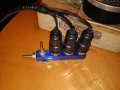
The four pole double throw relays I suggest are the much cheaper, non-sealed, versions of the P&B KHS17 series. Interchangeable and they do not really need those very expensive sockets. There are also some much cheaper multipole relays that have a goofy connection arrangement, I recommend avoiding them completely.
Those very nice VERY expensive screw terminal sockets are made for use in control panels, a different world from automotive in every aspect.
Those very nice VERY expensive screw terminal sockets are made for use in control panels, a different world from automotive in every aspect.