Facebook
 Google
 GitHub
 Linkedin
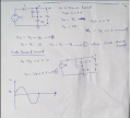
I am trying to solve a circuit with AC sources but to understand the problem i have drawn a circuit with DC

My major problem of understanding is since V1 is 1V and V2 is 2V, D1 is reverse biased or open circuit then if i measure voltage at Vout it will be V2 or 2V how? We are saying open circuit so V2 will not be connected to Vout. What i am missing here?
My major problem of understanding is since V1 is 1V and V2 is 2V, D1 is reverse biased or open circuit then if i measure voltage at Vout it will be V2 or 2V how? We are saying open circuit so V2 will not be connected to Vout. What i am missing here?