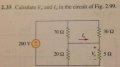
A question on transfinite quantities.

studiot

Joined Nov 9, 2007
4,998
Can a current flow between two points at the same potential or not?
I clearly stated "in a load".
I have so far carefully avoided comment on 'the circuit' that sparked off this thread.

That is because I agree with the Electrician - it is ill posed.
Perhaps deliberately by the lecturer to bring out a point.

But what point?

Let me ask a question or two first.

Suppose in the original circuit a second (third...) strap wire was connected. What would be the current in this wire?
Would it change the current in the other wire or the rest of the circuit?

Now let me ask these questions of WBahn's example of a 12v source and a 2 ohm resistor.

Add a second (third...) wire to the connection between the source and the load (Yes RB I will come to your comment about load)

Or better change the original solid wire for stranded.

Now what is the current in each strand?

Well, as I said before ( and I agree that 6 amps flow, make no mistake here), we need extra physics - in this case materials properties and crosssectional areas to answer these questions.

6amps flow but circuit theory regards this wire or assembly of conductors as a single node for circuit analysis purposes.

A single node does not (should not) have a 'voltage' across it, that requires two nodes. All points on the wire are part of the same node.

So back to my original statement.

Connect two nodes of a circuit at the same potential by a conductor of any value and zero current flows.

No inconsistency here. We can return to our circuit theory.

Note that it is this single node characteristic that allows us to stretch, bend, and redraw circuit diagrams to expand or contract individual nodes to put a drawing in its most convenient form.

Or as some lecturers do for effect, to put the circuit in its most confusing form.

If you redraw the original circuit (or WBahn's example) with the strap wire condensed to a single node, the short becomes immediately apparent (or the issue of 6 amps at zero volts goes away).

Please note that my example of a wheatstone bridge correctly identifies two separate nodes in a circuit at the same potential and discusses the current in a connection between them.

Similarly, my examples of an unconnected battery and an unpowered vacuum tube identify two nodes in a circuit.
A strap wire is a single node not two and does not constitute a load, according to the definitions of circuit theory.

As an aside, someone compared the original circuit to the mechanical question of an irresisible force and an immovable object.
That is not a good comparison because mechanics has an extra piece of physics to resolve that conundrum, unlike electric circuit theory, which does not. It all hinges on your definition of irrestible force and immovable object.
 
Last edited:

THE_RB

Joined Feb 11, 2008
5,438
Thanks for keeping this open-minded and less judgemental, it definitely makes for a more fun discussion. :)

OK, I'll play (back to your earlier statements);

This is the case in my example of two nodes in a circuit at the same potential.

This leads to the question I posed "what is the current if we connect with an ideal wire?"

Mathematically this leads to a 0/0 situation.
...
If I read you right, this is now a wheatstone bridge type layout, with "an ideal wire" ie 0 ohms, and since the two points are at the same potential you are stating;
I = E/R
=0v/0 ohms
And we know I to be zero (since there is no potential difference) so you have "proved";
0A = 0v/0 ohms
or
0/0 = 0

Now to analyse it... ;) I get zero divided by anything equals zero. The operation is really
0v/x ohms = 0 amps.

In which case, (in the real world), your "ideal wire" resistance can be replaced by ANY possible value of resistance and the math will always remain;
0/x = 0

I still consider that a "load" circuit, as it is not sourcing current, current can only flow via external influence. And I still place current (I) as the "master" item in that evaluation as we know the current must be zero (a credible real world number) and having zero in the calc ensures certain outcomes (such as if I=0 then E=0 and R is without effect.

So it seems you have either proven that in the real world 0/0=0, or you have proven that Ohm's law is not valid for all real world conditions that may occur in a circuit.
What are your thoughts on that?
 

WBahn

Joined Mar 31, 2012
32,970
If current can only flow via external influence, then it would seem that the external influence must be the master of the thing it influences.
 

studiot

Joined Nov 9, 2007
4,998
or you have proven that Ohm's law is not valid for all real world conditions that may occur in a circuit.
Of course it is not valid for all real world conditions that can occur in a circuit.
I have never suggested otherwise and I don't feel the need to prove it.

Ohm's Law is just one of many relationships that may pertain between the circuit variables of current and voltage.

Apply the wrong (inappropriate) mathematics and you will obtain the wrong answer (nonsense).

I do believe my comment was more general than just a wheatstone bridge (although I did refer to this as an example), I referred to any two nodes at equipotential in any circuit.

The point I didn't make properly earlier is that as soon as you connect them with a zero impedance strap wire you change the circuit by converting two nodes into a single node. This is not the case if you connect them with any real circuit element, whatever the relationship between current and voltage it follows. Two nodes then remain two nodes.

Have a look at my sketches in this thread that clearly exemplify the point.

http://forum.allaboutcircuits.com/showthread.php?t=89445

post#17

***************************************************


General Comment.

I think this thread brings out the fact that many have an unsound or incomplete definition of (at least some) the following terms.

Circuit
Circuit variables
Node
Branch
Circuit element
Terminal
Circuit element properties /parameters

It may be worth examining these to see what develops.
 
Last edited:

Tesla23

Joined May 10, 2009
560
How much current is flowing in a superconducting magnet that has zero resistance and zero volts across it?
I should have answered this earlier as it summarises some of the thread - you are asking how much current flows through a short circuit, knowing only that it is a short circuit! Clearly, as has been stated in more obtuse fashion in other answers, the current through a short circuit depends on what it is short circuiting.

An interesting thought experiment is to connect your superconducting coil to your 12V supply through a 2Ω resistor, and you see 6A flow. What happens if you connect two of these superconducting coils in parallel and then connect your 12V supply and 2Ω resistor?
 

Tesla23

Joined May 10, 2009
560
The point I didn't make properly earlier is that as soon as you connect them with a zero impedance strap wire you change the circuit by converting two nodes into a single node.
A single node does not (should not) have a 'voltage' across it, that requires two nodes. All points on the wire are part of the same node.
It is not necessary to perform the nodal reduction like you indicate, and if it is done it prevents you from calculating the current in the branch.

For the type of circuit you were discussing, where the requirement was to compute the branch current, it doesn't appear helpful to eliminate the branch:


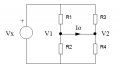
firstly note that this is pretty trivial and there are several simple ways to calculate \(I_0\), including mesh analysis. I'm talking about general solution techniques, which I suspect motivates studiot to merge the nodes.

Straightforward nodal analysis will fail for this circuit if you treat the two nodes at the ends of the \(I_0\) branch as individual nodes, as you get an infinite conductance joining them. I suspect this is what motivated you to combine them to one node.

The tool to cope with this for general circuits was developed back in the '70s and is Modified Nodal Analysis (MNA), this allows you to analyse a circuit which has nodes connected with perfectly conducting branches, and as a side benefit, it computes the currents in the branches. This is probably the most widely used circuit analysis technique today as it is the basis for Spice.

A simple example of where this would be used in Spice is in treating inductors for a DC analysis. Spice does not merge the nodes, it simply uses MNA to add perfectly conducting branches (for ideal inductors) in place of the inductor.

Another example in Spice is when you add a 0V source to a circuit and ask Spice to calculate the current through it, which is exactly the problem at hand.
 

Attachments

Last edited:

Tesla23

Joined May 10, 2009
560
Now let me ask these questions of WBahn's example of a 12v source and a 2 ohm resistor.

Add a second (third...) wire to the connection between the source and the load (Yes RB I will come to your comment about load)

Or better change the original solid wire for stranded.

Now what is the current in each strand?

Well, as I said before ( and I agree that 6 amps flow, make no mistake here), we need extra physics - in this case materials properties and crosssectional areas to answer these questions.
Indeed an interesting question, how is the current shared between conductors in a stranded conductor? What if some conductors are fatter than others? studiot suggests that this depends on the material properties and cross sections, and this is true if they have finite conductivity - we simply have a resistive current splitter. But what if they are superconductors? How is the current shared between two superconductors in parallel?

What if I have 1A flowing through a superconductor, so no voltage across the ends, and I bring an identical superconductor alongside and into contact? There is no voltage to drive a current through the second one - so does any current flow in it?
 

studiot

Joined Nov 9, 2007
4,998
Straightforward nodal analysis will fail for this circuit if you treat the two nodes at the ends of the branch as individual nodes, as you get an infinite conductance joining them. I suspect this is what motivated you to combine them to one node.
I also asked for other folks definition of a 'node' What is yours?(post65)

No I was not motivated to combine the 'nodes', in fact if you look carefully in the thread from which you extracted this circuit you will see that I have always maintained (in bold) that there is only one node (post 17 in that thread)

The situation in that thread is feasible and solvable and the solution is presented there. It only takes two lines and both the voltage and current are calculated as called for in the question, not as you suggest only the current.

The situation that inspired this thread we are currently debating in is not a feasible circuit connection, even in the ideal.

As regards superconductors, from the little I know of them they do not violate the law of conservation of charge.

So calculations of current available etc would be done, exactly as I have said for other unusual situations, on the basis of additional physics, in this case based on the total charge introduced.

Finally software.
Surely your software checks for zero impedance between nodes and returns an error if you enter this?
 
Last edited:

Tesla23

Joined May 10, 2009
560
6amps flow but circuit theory regards this wire or assembly of conductors as a single node for circuit analysis purposes.
All points on the wire are part of the same node.
These are unnecessary restrictions that simply make some circuits hard to analyse. Try to generalise your method of determining the current in the problem in the other thread. Take any complex circuit and work out the short-circuit current between any two nodes.

Your circuit theory has no concept of an ammeter - both ends of your ammeter are the same node. Yes, you can manually sort out the currents in each case, but there are simpler ways.

Compare that with the MNA way of analysing the circuit in the other thread. I'm not saying you should do it this way - I did it the way The Electrician showed on the other forum, but this technique generalises to arbitrary, complex circuits.


MNA allows you to write down the equations by inspection:

V1 * (G1 + G2) - G1 * Vx + Io = 0
V2 * (G3 + G4) - G3 * Vx - Io = 0
V1 - V2 = 0

where G1 = 1/R1 etc..

This treats the two ends of the wire with Io passing through it as separate nodes, but the third equation enforces the connection.

If, instead of the wire, you connected them with a voltaqe source with voltage Vs, then the third equation simply becomes

V1 - V2 = Vs

Finally software.
Surely your software checks for zero impedance between nodes and returns an error if you enter this?
One of my early circuit simulators I wrote certainly did this, but then I discovered MNA! 'Proper' software like Spice has allowed you to have zero impedance links between nodes forever.

If you are interested in MNA, here is some practical stuff:
http://qucs.sourceforge.net/tech/node58.html
A short circuit is modelled as a voltage source of 0V.
 

Attachments

WBahn

Joined Mar 31, 2012
32,970
I should have answered this earlier as it summarises some of the thread - you are asking how much current flows through a short circuit, knowing only that it is a short circuit! Clearly, as has been stated in more obtuse fashion in other answers, the current through a short circuit depends on what it is short circuiting.

An interesting thought experiment is to connect your superconducting coil to your 12V supply through a 2Ω resistor, and you see 6A flow. What happens if you connect two of these superconducting coils in parallel and then connect your 12V supply and 2Ω resistor?
You will have a total of 6A flowing in some combination of the two. How much is flowing in each can be determined several ways. On paper, you could simply integrate the governing differential equation since the relative inductances of the two magnets will determine how the current splits. From a more applied standpoint, you could monitor the current during the charging process and determine how much total energy was dumped into the fields. Since field energy is nonlinear with current, you can use that to determine how much current is in each inductor. If the inductances are the same, then the energy will be evenly split and both magnets will have the same field. If you really wanted to know, you would use magnetometer to measure the field in each magnet.

Note that since the magnets are superconducting and in parallel, they will shift current back and forth as needed in order to respond to changes in their magnetic environments.
 

studiot

Joined Nov 9, 2007
4,998
but the third equation enforces the connection.
My statement that there is only one node is equivalent to your third equation and is a voltage condition, which I specified earlier (all points in a node are at the same potential).

A node can comprise one or more branches.
In order to calculate the current in the wire we can do a simple branch analysis, as I showed in the thread.
Because of this currents may vary in different branches of the same node. this is the situation we have here.
If we have a zero potential path we set both branch current equal, as I have done.

So essentially you are calculating with a currents and a voltage constraint, I am calculating with voltages and a current constraint. These are mathematically duals and lead to the same answer.

Yes we can do an admittance analysis or something even more complicated. This is another way to avoid division by zero.

All successful methods must, as the Electrician pointed out avoid this pitfall.

You didn't respond to my comment on superconductors and the conservation of charge?
 

Tesla23

Joined May 10, 2009
560
My statement that there is only one node is equivalent to your third equation and is a voltage condition, which I specified earlier (all points in a node are at the same potential).

A node can comprise one or more branches.
In order to calculate the current in the wire we can do a simple branch analysis, as I showed in the thread.
Because of this currents may vary in different branches of the same node. this is the situation we have here.
If we have a zero potential path we set both branch current equal, as I have done.

So essentially you are calculating with a currents and a voltage constraint, I am calculating with voltages and a current constraint. These are mathematically duals and lead to the same answer.

Yes we can do an admittance analysis or something even more complicated. This is another way to avoid division by zero.

All successful methods must, as the Electrician pointed out avoid this pitfall.
As I pointed out, the power of the Modified Nodal Analysis technique is not that it easily analyses the circuit in the other thread, but that it easily generalises. Mind you, it does give the general solution to that problem pretty simply.

Your technique of putting ammeters inside nodes requires post processing of a nodal result to determine the desired branch current. This is not always adequate, for example if the branch current is a dependent variable in the circuit analysis.

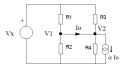
Let's try a slightly more complicated network, adding a current controlled current source as shown:


This is only slightly more complicated than the original circuit, and the MNA equations become:

V1 * (G1 + G2) - G1 * Vx + Io = 0
V2 * (G3 + G4) - G3 * Vx - (1 - α) Io = 0
V1 - V2 = 0

How does your solution technique compare?

By the way, the Modified Nodal Analysis technique is not MY technique, it is an established, widely used technique, extensively documented in the literature.
 

Attachments

studiot

Joined Nov 9, 2007
4,998
Tesla, why do you think there are simple and more complicated analysis techniques?

Hint : the original problem, along with the one currently under discussion were published in the homework section.
 

Tesla23

Joined May 10, 2009
560
You will have a total of 6A flowing in some combination of the two. How much is flowing in each can be determined several ways. On paper, you could simply integrate the governing differential equation since the relative inductances of the two magnets will determine how the current splits. From a more applied standpoint, you could monitor the current during the charging process and determine how much total energy was dumped into the fields. Since field energy is nonlinear with current, you can use that to determine how much current is in each inductor. If the inductances are the same, then the energy will be evenly split and both magnets will have the same field. If you really wanted to know, you would use magnetometer to measure the field in each magnet.

Note that since the magnets are superconducting and in parallel, they will shift current back and forth as needed in order to respond to changes in their magnetic environments.
I agree, and if the magnets are identical there will be equal currents flowing.

So this started me thinking about studiot's stranded conductor, if it is a perfect conductor, then each strand looks like small ideal inductor. If you connect two equal inductors together in parallel and start passing current through them, the DEs will cause the current to grow equally in each. I'm sure that the resultant equal current split is also the minimum of stored magnetic energy in the two inductors.

The interesting question is what happens when you have only one inductor and you pass a current I through it. It is perfectly conducting and so has no voltage across it. You then bring up a second inductor and connect it across the first. According to circuit theory there is no voltage to cause any current to flow in the second inductor and so it all keeps flowing in the first one, even though the stored magnetic energy could be halved if the current was to be shared between the inductors. To me this suggests that there is some physics missing from the circuit theory model.

The superconductor case is really interesting - I keep getting little gems from the most obscure threads on this forum. All you need to know is that superconductors exclude magnetic fields, and external fields will cause eddy currents to flow that generate cancelling magnetic fields so that inside the superconductor there is no field.

Imagine you have a cylindrical superconductor passing a current I. It will have a circumferential magnetic field. Now take an identical superconductor some distance from, but parallel to, the first. There is no current flowing in it. Bring it up near the current carrying superconductor. Eddy currents will be induced in the second one in such a way to cancel the magnetic flux created by the first one. The currents on the surfaces that are closest tend to cancel, and as you bring them together, at least some current is diverted to the outer edge of the second conductor. So if you bring a second superconductor up to a current carrying first one, then you will end up with some current passing through the second one, even though you are connecting it to two nodes which have zero voltage across them.

Also, as the new current arrangement results in a lowering of the stored magnetic energy, there will be an attractive force between the conductors, and the decrease in stored magnetic energy will be released as work done on the approaching conductor. (It's probably a pretty small force).
 

Tesla23

Joined May 10, 2009
560
Tesla, why do you think there are simple and more complicated analysis techniques?

Hint : the original problem, along with the one currently under discussion were published in the homework section.
I didn't post it in the homework forum, I thought that at least some folk here would be interested in things past circuit theory 101, but if it is too advanced let me know. I think that the MNA technique is actually simpler that your procedure.

But given that we are not in the homework forum, the best way to understand the differences between techniques would be to compare them, you say that your technique is a simple dual to what I used, I don't see that and it would help me understand if you would show how you would solve the circuit with the current controlled source.

By the way, it appears that the Modified Nodal Analysis technique is widely taught:
https://www.google.com.au/#q=modified+nodal+analysis+site:.edu+
so you may find it one day in the homework forum.
 

studiot

Joined Nov 9, 2007
4,998
I am not trying to promote any particular method, though I have no beef with MNA, it is a good method. Since you have introduced it there is no need for me to pursue it. Equally I have acknowledged further methods introduced by others, without trying to belittle any of them.

This particular thread was started, quite rightly in my opinion, by ernie as a "spin off" about the validity of certain mathematical procedures, in particular division by zero, in the maths forum.

So this is not the thread or forum to promote particular circuit analysis methods.

I am finding it increasing difficult as this subject is obviously of wide interest to co ordinate the several threads and persons now being drawn in and the fundamental issues being raised.

I therefore propose to start a new thread with a properly (I hope) thought out first post to try to rationalise things.

In particular I will adress the issues of Ohm's law and 0/0 because this is a real issue when we ask the question "What is Ohm's law at a point?" I am sure you are aware of the issue in electrodynamic theory and why the simple E=IR is inadequate/insufficient.

It is difficult to know whether the appropriate place is the maths or physics section but I hopr to make a start later today. Probably too late for you in OZ till tomorrow but wath this space.
 

WBahn

Joined Mar 31, 2012
32,970
The interesting question is what happens when you have only one inductor and you pass a current I through it. It is perfectly conducting and so has no voltage across it.
No point reading any further since you are starting from a premise that is fundamentally wrong. The voltage across an inductor is not proportional to the current flowing through it, but the rate of change of that current. When you change the field of a superconducting magnet you do it by applying a voltage across it, which established a ramp rate for the current. If the voltage is positive, the magnetic field increases in intensity while if the voltage is negative the field intensity decreases.
 

Tesla23

Joined May 10, 2009
560
No point reading any further since you are starting from a premise that is fundamentally wrong. The voltage across an inductor is not proportional to the current flowing through it, but the rate of change of that current. When you change the field of a superconducting magnet you do it by applying a voltage across it, which established a ramp rate for the current. If the voltage is positive, the magnetic field increases in intensity while if the voltage is negative the field intensity decreases.
So you are saying that it is not possible to have an ideal inductor with a steady current passing through it? If this were indeed to happen, wouldn't you concede that the voltage across the inductor would be zero as the current wasn't changing?

All I am saying is that if you happen to find an inductor with a steady current passing through it, and if you then were to bring a second one up and connect it in parallel, then there is no mechanism in circuit theory to cause the current to share with the second inductor, even though this sharing will reduce the stored magnetic energy.
 

WBahn

Joined Mar 31, 2012
32,970
So you are saying that it is not possible to have an ideal inductor with a steady current passing through it? If this were indeed to happen, wouldn't you concede that the voltage across the inductor would be zero as the current wasn't changing?

All I am saying is that if you happen to find an inductor with a steady current passing through it, and if you then were to bring a second one up and connect it in parallel, then there is no mechanism in circuit theory to cause the current to share with the second inductor, even though this sharing will reduce the stored magnetic energy.
Ah, I think I misinterpretted your post and thought you were saying that a zero resistance inductor would always have zero voltage across it because the resistance is zero.

But I see what you are getting at and, yes, there would be no shifting of current. But this is not the big quandry that it might seem. Consider a tank of water sitting on a table and we sit a second, empty tank next to it and then insert a tube the comes up out of one tank, goes over the rim, and down into the other tank. The total gravitational energy stored is more than if the two tanks had the same water level and there is even a path for water to travel. But if the tube wasn't filled with water when it was inserted, then there is an "activation" energy that must be overcome in order for an equilibration to happen. Without that impetus, the system will be happy sitting there with more than minimum energy.
 
Top