Facebook
 Google
 GitHub
 Linkedin
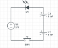
Imagine you have a single 5V voltage source with an LED attached directly to it. Now all you have to do is complete the circuit such that the LED lights up. The challenge is that the LED must connected to the source, NOT at the anode...but at the CATHODE!

Attachments
-
 3.2 KB Views: 0