Facebook
 Google
 GitHub
 Linkedin
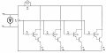
I am trying to use the parts I have on hand, to build an active load for testing the output of DC power supplies. The idea is based on this design: https://www.deeptronic.com/electronic-circuit-design/variable-dummy-load-for-power-supply-testing/
But uses MJ11016 NPN darlington transistors in parallel for higher power https://www.onsemi.com/pub/Collateral/MJ11012-D.PDF
I have attached a drawing of the schematic. Please let me know if I've done something drastically wrong here! I have some giant diodes and will be inserting one for polarity protection, but I really want to know if the basic circuit is all wrong.
If you have an idea for improvement please let me know that as well.
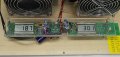
Attachments
-
 221.7 KB Views: 43