9v Power Supply Advise

Thread Starter

liamstears

Joined Jan 31, 2013
26
First of all I'm sorry but I'm not great with the theory side behind electronics but I'm good with a soldering iron so I'm here in the hope of getting some help with a power supply design. I need a very large 9v power supply but each output needs to be isolated so I basically was thinking of combining multiple 9v power supply into 1 box. I need 13 9v outputs that can offer up to 600ma and 1 9v output that can offer up to 1.5a. I need the output power to be as clean as possible and don't want interference. I also need to keep costs as low as possible.

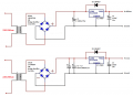
I've done some research and looked at various designs and come up with the below. The top circuit I would duplicate 13 times and then do the bottom circuit once. All IC's will have heatsinks (with a bigger one on the higher power circuit). My questions mainly relate to component choices and understanding how many amps are needed. So my questions are:

Diodes or bridge rectifiers? Bridge rectifier will be cheaper, have I spec'd these correctly?

Capacitors - These will be low esr and need low ripple so have I chosen good caps?

Is D5 required? I read it helps if there is a short circuit on the output?

Should I have some filtering on the mains input? Maybe something like this: https://www.ebay.co.uk/itm/164359837755
Will 3a mains input be enough to power all 14 circuits? I don't know what the mains draw would be for this

Biggest question, transformers. What voltage would be best? 9vac? 12vac? or even higher? and then once voltage is chosen how many VA will I need to power each circuit?

Thanks in advance for any/all help given
 

Attachments

Thread Starter

liamstears

Joined Jan 31, 2013
26
As a follow up I can get 12vac dual output 0.75va x2 transformers for a good price, would 1 output 0.75va at 12vac be enough to power 1 circuit?
 

dl324

Joined Mar 30, 2015
16,943
Diodes or bridge rectifiers? Bridge rectifier will be cheaper, have I spec'd these correctly?
EDIT: For some reason I had it in my mind that you wanted 1.5A and 3A outputs. Adjust my comments accordingly.

1N4007 are rated for 1A continuous, so they're insufficient for a 1.5A output. You've over specified the voltage ratings for both. Using a 1.5A bridge rectifier at 100% is probably unwise. We don't normally operate components at 100% of their specification. If you choose to do that, you need to investigate derating requirements.

Similar case for the 3A circuit.
Capacitors - These will be low esr and need low ripple so have I chosen good caps?
You don't give a part number so we don't know the ripple current specs. Whether 1000uF is appropriate depends on the transformer secondary voltage and the current draw.
Is D5 required? I read it helps if there is a short circuit on the output?
It protects the regulator when the input is shorted. If you short the output, D5 will be reverse biased. The regulator will protect itself.
Should I have some filtering on the mains input?
Not likely.
Will 3a mains input be enough to power all 14 circuits? I don't know what the mains draw would be for this
Yes. To the first order, you'll draw less than 1.5A from mains.
Biggest question, transformers. What voltage would be best? 9vac? 12vac? or even higher? and then once voltage is chosen how many VA will I need to power each circuit?
9VAC is too low. The peak at the filter cap will be 9V*1.414-1.4=11.3V. 7809 will have a dropout voltage of 2-3V.
 
Last edited:

Thread Starter

liamstears

Joined Jan 31, 2013
26
Thank you all for the replys

It seems this method would be extremely expensive as a transformer of that va is over £10 each and I would need multiple to power all 14 outputs

There must be an easier way of doing this maybe someone can help? I need 14 isolated 9vdc outputs, 1 needs to supply 1.5a, the rest ,600ma...
 

dendad

Joined Feb 20, 2016
4,479
If you do need all these supplies isolated, how about looking for a stack of plug packs from a second hand store?
There are be many such plug packs tossed out. Most may be unregulated, but as you intend to build a 9V regulator, that will not be a problem.
Look for 12V 1A supplies, not 9V ones, unless they include a regulator.
If the plug packs are light, they will be switch mode types, so look for heavier ones that have a transformer inside.
Another clue to identify switch mode supplies will be if the mans input is rated as 100 to 240V.
The supply you linked in post #10 is a switch mode type, and if you are concerned about noise, they may not be the best to use.
If 7809 regs are hard to get, LM317 regs are adjustable. BUT!!! they have different connections to the LM78xx series.
There are quite a few ready made boards available for these.
What are you driving with these supplies?
 

BobTPH

Joined Jun 5, 2013
8,998
So there is no common connection in these 14 circuits? Because if there is, you will be removing the isolation. If you are worried about one device switching causing the supply voltage to bounce in other devices, use a 12V supply and 14 9V regulators.

Edited: And, if you are worried about ground bounce, ground each one separately to the supply.

Bob
 

Thread Starter

liamstears

Joined Jan 31, 2013
26
This is clearly going to be more difficult than originally anticipated and using individual circuits using transformers is going to be big, bulk and heavy so I think I have to redesign this

My thoughts now are to use a high power switch mode power supply to power the regulators but then use flyback transformers and common mode chokes to isolate the outputs and help with noise

Anyone have any comments/advice on doing it this way?
 

MrChips

Joined Oct 2, 2009
30,823
You need to take a different approach in your quest to find a viable solution.

Isolation
Isolation usually refers to galvanic isolation. This can be implemented in two ways, using inductive coupling via transformers, and optical coupling via opto-isolators. With multiple sensor inputs it is common to have all sensors referenced to a common potential which is usually earth ground or circuit common. This contradicts having galvanic isolation. If there is a genuine reason to have circuit isolation then sensor data can be digitally encoded and transmitted across opto-isolators or fibre-optics.

Noise
Undesirable noise can be introduced into sensitive equipment in three ways:
1) External EMI
2) Internally induced circuit noise and EMI
3) Instability, environmental or otherwise

To assume that non-isolated PSU will be a source of noise is a red herring. One cannot mitigate the adverse effect of noise until one identifies the source and categorizes the type of noise.

In order for us to give advice you would have to tell us what it is that you are trying to power.
 
Top