Facebook
 Google
 GitHub
 Linkedin
Hi,
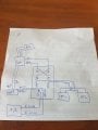
Im rewiring and upgrading my kids ride on car and for the life of me i cany get the relay to work for reverse. It all works in FWD although when you select REV it still goes FWD!
Here is my wiring diagram that i am using. Any thoughts?
Im rewiring and upgrading my kids ride on car and for the life of me i cany get the relay to work for reverse. It all works in FWD although when you select REV it still goes FWD!
Here is my wiring diagram that i am using. Any thoughts?
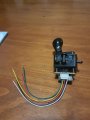
Attachments
-
 157.1 KB Views: 37