I think we need to know a bit more about the controller. It seems to have 5 output wires. What do they all do? Can you post a link to its datasheet?
Edit:
Are you sure you have identified pins 7 and 8 correctly? The relay has markings on the top which purport to show a 'bottom view', which will be a mirror image of the pin positions as seen from the top.
Are you supplying 24V to the relay coil? If so, the LED should light.
This looks like the socket you are using.
Make up a bidirectional LED tester ....
I've made these up with heat shrink tubing and a couple of foot long wires. Use a red wire and green wire, connected so the red LED lights when the red wire is connected to positive. Then you can read the supply polarity from the LED that is lit. This is a very handy little bit of test gear.
Place that instead of the motors so it is easier to test, and it will rule out high current problems.
Ignore the controller switch for a bit, just hook the relay to a battery or 24V power supply and you should get the LED to change colour as the relay operates.
With that working, then add the controller switch.
I may have led you all down the garden path a little-sorry. Wasn't intentional, its just my lack of understanding and terminology.
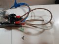
The "switch" to select FWD & REV is not actually a switch (well i dont think so) as the "selector" has a little pcb attached with 5 wires and pin 1 seems to be the common when the gears are selected. Which went to the OEM pcb(no longer works so trying to bypass)
So ive managed through trial and error, connect the motor output from the controller to the coil pins (7&8) with the FWD/REV connected inline.
I have then connected the motor output pins on the relay (5&6) to the motor.
When i press the accelerator for REV you hear the coil energise.
So i think im on the right track.
Question now is, what do i connect to pins 1,2,3&4?
Is it +ve to pins 1&3 and -ve to pins 2&4?
We probably cannot help with the switch as it is not a standard part.
You could measure the continuity between all the wires on each position and post that table so help might be available.
 Facebook
 Google
 GitHub
 Linkedin