74LS93 glitching reset

Thread Starter

corasan

Joined Jul 18, 2023
35
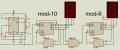
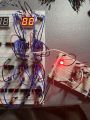
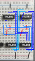
I have here a 60-second counter using 74LS93. The Proteus simulation works fine, but when I tried to build the circuit on a breadboard, I encountered some glitches in its output. The most common glitch I observed is when it resets, it goes from 59 >> 20 (instead of 00); there are more glitches, but this is the most common. The glitches all give inaccuracies after resetting. I used a separate 74LS08 for resetting and clocking since I observed more glitches when the clock and reset inputs are on the same IC. I know I could just use the same AND gate to reset and clock when it reads 1010, but I find it more effective to use 1001 to clock the mod-6 counter since CKB is active low. 1010 only exists for a few milliseconds, making clocking inefficient in the breadboard circuit. I find it hard to troubleshoot the glitches as I have the exact connections with my simulation design.

How can I eliminate the resetting glitches?
Could this be an issue with the ICs' current inputs?
Do I need resistors for the AND gate inputs?
--If yes, what resistor value?
 

Attachments

Thread Starter

corasan

Joined Jul 18, 2023
35
Do I need to put decoupling capacitors parallel to the power supply of every 74LS48, 74LS93, 555, and logic gate ICs (OR, AND, NOT) in the entire circuit? Also, do I need decoupling caps on the I/O pins of the mentioned ICs?

1690387362399.png
 

MrChips

Joined Oct 2, 2009
34,628
On a commercial PCB I would put a 0.1μF ceramic capacitor at every logic IC.

On a prototype breadboard, put 0.1μF across the power rail at every three ICs, at minimum, one capacitor on every row of ICs.
Put one 100μF where Vcc and GND enters the board.
Put one 10μF across Vcc and GND at the 555-timer IC.
Avoid using NE555 or LM555. Use LMC555, TLC555, ICM7555 instead.

No capacitors are required at any signal or I/O lines.
 

WBahn

Joined Mar 31, 2012
32,703
Don't leave clock lines floating -- that's asking for trouble. In general, don't leave any input floating unless the data sheet explicitly indicates that it is okay to do so.
 

Thread Starter

corasan

Joined Jul 18, 2023
35
Avoid using NE555 or LM555. Use LMC555, TLC555, ICM7555 instead.
What's the reason why these models should be avoided? Currently, I am using an NE555. I'll try to find your suggested 555s from my local stores.


don't leave any input floating unless the data sheet explicitly indicates that it is okay to do so.
Which part of the datasheet can I find these specifications? I can't seem to find it.
 

MrChips

Joined Oct 2, 2009
34,628
What's the reason why these models should be avoided? Currently, I am using an NE555. I'll try to find your suggested 555s from my local stores.
NE555 and LM555 have high current output (200mA). Every time the output switches state they throw a lot of noise spikes into the supply lines.

LMC555, TLC555, ICM7555 are CMOS versions of the 555-timer. They consume much less current but can only drive 50mA at the output. The noise generated on the supply lines is much lower than their BJT counterparts.
 

dl324

Joined Mar 30, 2015
18,219
What's the reason why these models should be avoided? Currently, I am using an NE555.
Some are concerned about shoot-through on the output where there's a brief short of the power supply. This occurs on every CMOS output too.

If you follow supply decoupling recommendations, it isn't a significant problem. There are a huge number of circuits using 555 without issues. I've personally used them in hundreds of circuits and have never traced a problem to the timer output switching. I've never used a CMOS version in any of my designs.
I'll try to find your suggested 555s from my local stores.
Before going with a more expensive part, try adding an electrolytic and ceramic cap on the power supply near the timer to eliminate problems with glitches on the supply.
Which part of the datasheet can I find these specifications?
The rule of thumb is to never leave any inputs on logic devices floating.
 

Thread Starter

corasan

Joined Jul 18, 2023
35
I managed to minimize the glitches by lowering my supply voltage to 3.3V, as there are still frequent glitches with 5V even with the decoupling ceramic capacitors. Also, when I tried to put decoupling capacitors on all the 74LS93 counters, the glitches became more present. Hence, I only put the decoupling caps on the first-digit (mod10) counters.

When using an oscilloscope to monitor the DC waveforms, which component/s should I check for noise? Could you guide me on how I could troubleshoot noise reductions using an oscilloscope for future projects?
 

WBahn

Joined Mar 31, 2012
32,703
Which part of the datasheet can I find these specifications? I can't seem to find it.
You won't find it in most data sheets because most parts are not guaranteed to function properly with inputs left floating. The specifications are all given with defined voltages at the inputs. Those occasional parts that are designed to allow certain pins to float will make that very clear, not only because it is not the norm, but because it is a specific feature that they want you to know about.
 

crutschow

Joined Mar 14, 2008
38,316
Also, when I tried to put decoupling capacitors on all the 74LS93 counters, the glitches became more present.
Then something is seriously wrong.
How are you measuring theses "glitches".
Are you using a 10:1 probe with the probe ground lead directly connected to the breadboard signal ground?
 

drjohsmith

Joined Dec 13, 2021
1,549
You have a few things going on here.

as a general first , I'd say look at unplugging everything apart from the 555, and "play" with that

So those plug in boards are great , BUT, they have a few known problems
a) these look new, but the contacts very easily become very un reliable
b) inductance / capacitance. The long "bus bars" on every pin , form a capacitance / inductor circuit
which makes edges "ring" , and it very hard to propagate high speed currents
c) Coupling, the long "bus bars" , tend to easily couple currents form one to the other, especially if one has a high impedance input

You might not me running at a high speed clock, but an edge that rises 0 to 5v in say 2 ns, has frequency components that are needed up to many 10 of MHz,

Generally, work on assumption that every input to a logic chip needs to be driven, either by other logic or a pull up down.
it never does harm pulling a input to how you want the pin, it shows you have read the data sheet for the chip. Internal pull ups tend to be fairly large, 50K plus, so putting your own external resistance , stops the input from picking up random inputs if there is no internal resistance and does no harm if there is internal pull up / down.

A scope is good at lying...
that long ground wire on the probe, is actually terrible for digital signals
its ok for a quick look see, but you need to use a short ground to get a good signal,
not helped if you just earth the scope probe randomly onto somewhere on the board.

Logic chips such as the LS , are very good noise generators
they take relatively large lumps of power in relatively short spikes,
Each LS chip needs a decoupler , 10 or 100 nf ceramic, directly on the Power pin of the chip, and a short conection back to the ground. these plug board. They need to be ceramic , to cope with the high frequency needed
The plug board itself, needs ot have a "bulk" decoupler on it , the wore link from one bus bar to the main board is just not capable of supplying the short high current spikes needed.
typically a 100 uf electrolyte on each of the boards would be used.

As for the 555,
That is a great chip, but.
it operating principle is a small current through a large resistor , and detect the a small voltage change on a high impedance input, and it can dump a big current out.
High impedance means its very sensetive to external currents, a small current / large resistance is veyr sensetive to small current changes, and the large current out , tends to put a big ripple on the power supplys that cause disturbance...
Its a lot better than trying to make the circuit yourself from transistors, but be careful

this might be interesting
https://www.google.com/search?q=ne5...#fpstate=ive&vld=cid:60c4f4d4,vid:ABWU7FlM1T0
 

MrChips

Joined Oct 2, 2009
34,628
Some are concerned about shoot-through on the output where there's a brief short of the power supply. This occurs on every CMOS output too.

If you follow supply decoupling recommendations, it isn't a significant problem. There are a huge number of circuits using 555 without issues. I've personally used them in hundreds of circuits and have never traced a problem to the timer output switching. I've never used a CMOS version in any of my designs.
Before going with a more expensive part, try adding an electrolytic and ceramic cap on the power supply near the timer to eliminate problems with glitches on the supply.
The rule of thumb is to never leave any inputs on logic devices floating.
555-timer IC is a great little chip and very useful and handy in many situations.
BJT versions of the 555-timer IC, such as NE555 and LM555 are used in millions of applications without causing any problems.
If the application is not sensitive to power line glitches then all is well.

If you have an RC monostable multivibrator circuit with tight requirements on the output pulse-width, you will encounter shorter pulse-width in a noisy environment. The analog comparator on the RC is looking for when the voltage on the capacitor reaches a given threshold voltage. Noise in the system will cause the monostable to switch earlier than designed. This is what happens when you have a BJT 555-timer on board. CMOS versions of 555-timer reduces the noise generated on the circuit.
 
Top