Facebook
 Google
 GitHub
 Linkedin
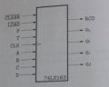
The 74LS163 is a completely synchronous counter, that means all updates of the states occur when the clock CLK is activated. The circuit is a 4 bit counter, that means it has 2^4 = 16 states. Every state sj, is given by the fourtiple Q = (qd, qc, qb, qa), where qa is least significant, as is binary code of the state index j. In the figure of the counter the available inputs and outputs are shown.

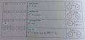
The counter is affected by the input vector ( CLEAR', LOAD', P, T, D, C, B, A) according to the table:

Except that the state variables are available there is yet another output RCO (Ripple Carry Output). It is given by the following:
RCO = qd ^ qc ^ qb ^ qa ^ T.
("^" = "AND")
So RCO becomes 1 when the counter should go from 15 to 0. This can be used to construct a counter with other lengths than 16.
For the second task, to make a 2Hz counter to create output signals that are 1 and 0.1 Hz respectively. There should be some delay that makes the first signal count only count once when the clock counts twice, and the second signal should only count once every 20th time the clock counts. So I guess there must be some circuit that creates this delay. But what kind of circuit does that?
Please help the best you can")
Except that the state variables are available there is yet another output RCO (Ripple Carry Output). It is given by the following:
RCO = qd ^ qc ^ qb ^ qa ^ T.
("^" = "AND")
So RCO becomes 1 when the counter should go from 15 to 0. This can be used to construct a counter with other lengths than 16.
Task 1
Let the counter's input be (1, RCO', 1, 1, d, c, b, a) where the date signals a, b, c, d comes from a binary coded number according to number=(d, c, b, a).
Since the counter no longer restarts from zero it is now a modulo-X counter. Express X using the specified number number.
X = f(number) =____________________
How do you solve these tasks? If we start with the first one, what happens when RCO' goes into LOAD? What does that do? What does LOAD mean? What does parallel LOAD mean? How can we from this express X using number?Task 2
Realize a modulo-10 and a modulo-2 counter, according to the previous task.
Assume that the counters are clocked with the 2Hz clock. How should they be connected to get two output signals with the frequencies 1 and 0.1 Hz respectively?
Draw a schematic of the interconnection of the counters. Observe that the system should be synchronous, that means both counters should use the same clock.
For the second task, to make a 2Hz counter to create output signals that are 1 and 0.1 Hz respectively. There should be some delay that makes the first signal count only count once when the clock counts twice, and the second signal should only count once every 20th time the clock counts. So I guess there must be some circuit that creates this delay. But what kind of circuit does that?
Please help the best you can
Attachments
-
 39.6 KB Views: 672
 -
 89.3 KB Views: 652
Last edited: