 Facebook
 Google
 GitHub
 Linkedin
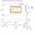
I am trying to understand how the 74ls163 works. I am building a z80 computer and added on a serial port using the attached schematic.
This print shows 307,692 hz comming out of the 74ls163 off pin Qd going to the RXc and TXc input to the 8251 USART. I built this circuit
and measured 4mhz coming from the clock circuit as shown but after the 74ls163 divides it down I am suppose to have 307,692 hz . I am measuring
907khz on pin Qd. I have checked the circuit wiring over and over but found no errors. I know this 74ls163 is a counter used to divide down the 4mz
but really have no idea of what is going on with it to do this division. It seems to have a 74ls00 as well that helps clear it out. Its just hard for me to look at it and tell how it works. I know it is 4 bit counter and that each flipflop divides by a different value. One Flip Flop = divide by 2 .. I think but can someone elaborate on what value it divides after that.
Could someone please help me understand this 74ls163 better in this circuit.
Thank you some much in advanced.
Mike
Attachments
-
 133.4 KB Views: 15


