74HC161 - Output problem.

Thread Starter

M12341234M

Joined Jun 15, 2019
5
Hi,

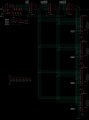
I am currently working on a project involving the following schematics.

Bildschirmfoto 2019-06-15 um 18.50.42.png

Now, the 74HC161 works fine with the 74HC157 disconnected. (The chip counts and the LEDs light up as expected)
But as soon as I connect the 74HC161, the outputs of the 161 remain low.

(All of these chips are 74HCxxx's).

Am I missing something?

Thank you in advance!
 
Last edited:

djsfantasi

Joined Apr 11, 2010
9,237
There are a couple of missing details.
  • What is your supply voltage?
  • What are the specs for the LEDs?
  • What are the outputs of the ‘157 connected to?
  • What are the inputs P_T_n?
Sorry for all the questions. Yet the answers are something you should know and have included in your post. And, I have more questions!

What is the high voltage output current of a pin and the total sourced current of the ‘161? Without the LED specification, the LED resistor values and the supply voltage, I can’t calculate the current draw. It’s possible that by connecting the ‘157, you’ve exceeded the ratings of the ‘161.
 

Thread Starter

M12341234M

Joined Jun 15, 2019
5
Sorry for the missing details.

The supply voltage is +5V.
The forward voltage of the LEDs is about 2,5 Volts - with a 510 Ohms current limiting resitor the current is about 5mA per LED.
The outputs of the 157 go straight to the address inputs of (in total) 4 at28c64 EEPROMs.
The signals P_T_n are signals to set the programming address, when the multiplexer switches to B inputs. These are currently tied to ground.

So in general I have a 20mA total current draw. 161s datasheet says the total max current draw is +-25mA.

I also tried disconnecting the LEDs completely but the same error occures.

Thanks for your quick reply.
 

djsfantasi

Joined Apr 11, 2010
9,237
Interrupt one input to the ‘157 and measure the current to the input.

It should be no larger than 1mA.

Both when the input is ~5V and 0V.
 

OBW0549

Joined Mar 2, 2015
3,566
Your diagram shows pins 3-6 of the 74HC161 floating. They should be tied either high or low, not left floating since doing so could result in erratic operation.

Other than that, I don't see anything in your diagram that suggests you should be having the problems you're seeing. Are you sure your wiring is correct? Both power and ground connected to each IC? Is there a decoupling cap (100 nF or thereabouts) connected from Vcc to Gnd on each chip?

Can't think of anything else...
 

Thread Starter

M12341234M

Joined Jun 15, 2019
5
I applied 5V directly to the 157 with the 161 disconnected and the current draw was 4,6mA - with the LED connected.

I tried grounding the 161s input pins too but that didnt work.

I have multiple decoupling caps around the chip, all 100nF.
 
Last edited:

ericgibbs

Joined Jan 29, 2010
21,439
hi M,
Can you confirm that it is really a 74LS157 .?
Also please post a photo image of the project layout showing the IC's.
Have you tried a replacement LS157.?
E
 

Thread Starter

M12341234M

Joined Jun 15, 2019
5
No currently these are 74HC157s but I also tried 74LS157.

Sorry for not having names in the layout.

IC50 - is the 161
IC61 - is the 157
and
IC51 - is one of the EEPROMS

*I added more decoupling caps that arent shown in the layout.
 

Attachments

ericgibbs

Joined Jan 29, 2010
21,439
hi M,
It appears on your PCB tracking that the +Vcc for the LS157 is on a different track to the LS161.??
Check the LS157 has +Vcc to ensure that you have +5V on that pin.
Without a +Vcc that LS157 could pull down the signal line inputs from the LS161
E
Update:
Assuming that your PCB copper is only double sided.???
Where are the 0V pins of the IC's connected too.??
 

Attachments

Last edited:

Thread Starter

M12341234M

Joined Jun 15, 2019
5
I checked the VCC pins and they are all at +5V.

Each side has a ground plane and all ground connections are connected properly. (2 Layer Board)

I tried another thing:

When I connect everything like the schematic shows, but with the 157s Outputs disconnected, the LEDs light up.
And the 157s outpus work correctly too.

So I guess the problem isnt with the 161 or 157 but with the address lines that go to the EEPROMs !?
 

Attachments

Last edited:

ericgibbs

Joined Jan 29, 2010
21,439
hi,
Do you have diagram showing the complete circuit and a fragment of code that sets the I/O pins of the MCU, you could post?
E
 

eetech00

Joined Jun 8, 2013
4,705
I checked the VCC pins and they are all at +5V.

Each side has a ground plane and all ground connections are connected properly. (2 Layer Board)

I tried another thing:

When I connect everything like the schematic shows, but with the 157s Outputs disconnected, the LEDs light up.
And the 157s outpus work correctly too.

So I guess the problem isnt with the 161 or 157 but with the address lines that go to the EEPROMs !?
Remove all the EEproms and if possible the device that writes (or addresses) the EEproms, then re-install the 161 and 157….report the results.

eT
 
Top