7475N latch problem

Thread Starter

lab-specialist

Joined Nov 25, 2009
11
i am back with a new question

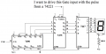
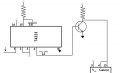
in building a circuit that only updates the display every second, i am using a 7475N between the counter and the decoder for the 7-segment display

i am seeing a strange behavior from the 7475N

on the chip, pins 4 & 13 are to be connected and they are used to gate (or latch) the data from the D's to the Q's

there is a positive voltage of @ 1.6 V on both pins 4 and 13 causing a problem for when the timing circuit goes to latch the data.

why is there 1.6 Volts on the gate pins??

please advise
 

Thread Starter

lab-specialist

Joined Nov 25, 2009
11
modified my question:

i have removed any and all connections to my 7475N with the exceptions of 5V and GND (on pins 5 and 12, respectively)

still, pins 4 and 13 float 1.6 Volts, so unless these pins are tied to gnd, the latch constantly updates itself

i put a transistor switch between the pulse generator(74221) and pin 4 of the 7475N and it works, however, this shouldn't be necessary
 

SgtWookie

Joined Jul 17, 2007
22,230
Gee, I still don't see a schematic.

A schematic is really a basic requirement. It's worth a thousand words, easy.

It will help us answer your question very quickly.

Without a schematic, the thread could go on for many pages and not get resolved.
 

beenthere

Joined Apr 20, 2004
15,819
Just one note - logic IC inputs always float up to the switching point and then cause oscillations. Unused inputs must be pulled up or tied to ground in order for the IC to function predictably.
 

Thread Starter

lab-specialist

Joined Nov 25, 2009
11
here is a quick schematic

i am wanting to latch the gates by sending a positive 5V pulse from a 74221 to the 4 and 13 inputs of the 7475.

again, the problem is, pins 4 and 13 have 1.6 volts on them and therefore the gate is always open and the 7-segment updates itself all the time
 

Attachments

Wendy

Joined Mar 24, 2008
23,798
Just one note - logic IC inputs always float up to the switching point and then cause oscillations. Unused inputs must be pulled up or tied to ground in order for the IC to function predictably.
Actually, TTL tend to assume a high if not connected. CMOS goes to an intermediate state that is a problem. Back in my college days TTL was king, CMOS was just being invented.

The high will do as you want, but you must give this input a firm ground to turn it off.
 

Thread Starter

lab-specialist

Joined Nov 25, 2009
11
that is what i have done

between the 74221 and the 7475 i put a npn transistor switch...and it works

however, this addition was not required some time ago

i am not sure what had changed

schematic to follow:
 

Attachments

Last edited:
Top