Facebook
 Google
 GitHub
 Linkedin
I also check your new gen from 38 post.
http://forum.allaboutcircuits.com/attachment.php?attachmentid=61172&d=1383876504
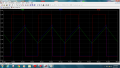
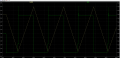
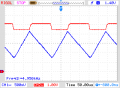
And here you have the results:
C1 = 100nF; F = 4.95Khz

C1 = 10nF; F = 24.27Khz

http://forum.allaboutcircuits.com/attachment.php?attachmentid=61172&d=1383876504
And here you have the results:
C1 = 100nF; F = 4.95Khz
C1 = 10nF; F = 24.27Khz
Attachments
-
 6.8 KB Views: 78
 -
 7.3 KB Views: 75
Last edited:
")