7 segment display for only 0,1,2

Thread Starter

dyn_o

Joined May 29, 2017
35
Hy,

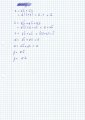
I want to use a 7-segment display to display only 0,1, and 2. So I think that as I only want to display 3 numbers I only need 2 input bits.

The truth table is :
truth table.jpg

I do karnaugh to obtain the function for each segment and then I wire, but 0,1,2 doesn’t display.

But when I use 4 bits input and do karnaugh to display from 0 to 9 it works.

So my question is , it is necessary to do karnaugh on 4 bits and for the numbers from 0 to 9 to only display 0,1,2 ?
 

dendad

Joined Feb 20, 2016
4,451
Please put up a circuit.
You have not supplied any information on the devices you are using so it is just about impossible to help you.
 

WBahn

Joined Mar 31, 2012
29,978
You need to show your circuit, preferably for both your 4-bit solution and your 2-bit solution. Otherwise we have no way to even reasonably guess what you might be doing wrong.
 

WBahn

Joined Mar 31, 2012
29,978
Notice that you are using 'a' and 'b' for two different things. That's a recipe for disaster.

Look at your equation for segment 'b'. While your equation works, notice that your table has nothing but 1 entries in it, so why can't you just set 'b' = HI?

Since you don't care what the output is for the last row of your table (a=HI, b=HI), can you see how you can simplify the expression for segment 'g'?

I can't tell for sure, but it looks like the common pin on the display is labeled 'CA' for "common anode", but the image resolution isn't too good and so it could be 'CK' which might indicate "common cathode". But you say that it worked when you did the full logic for a four bit input. Did you use this same display?

What happens if you just directly tie the display inputs HI or LO to create the digit '2', does that work?
 

Thread Starter

dyn_o

Joined May 29, 2017
35
Look at your equation for segment 'b'. While your equation works, notice that your table has nothing but 1 entries in it, so why can't you just set 'b' = HI?
Ok I just did it.

Since you don't care what the output is for the last row of your table (a=HI, b=HI), can you see how you can simplify the expression for segment 'g'?
g = b

But with b = HI and g = b it still doesn't work.

I can't tell for sure, but it looks like the common pin on the display is labeled 'CA' for "common anode", but the image resolution isn't too good and so it could be 'CK' which might indicate "common cathode". But you say that it worked when you did the full logic for a four bit input. Did you use this same display?
It's CK so it goes to GND, and yes I did use the same display and it worked.

What happens if you just directly tie the display inputs HI or LO to create the digit '2', does that work?
Yes it works when I directly tie the display inputs HI or LO to create de digit 2.
 

WBahn

Joined Mar 31, 2012
29,978
Yes it works when I directly tie the display inputs HI or LO to create de digit 2.
How does it "not work"? Does it not display anything at all, or does it display something but not the right thing?

When you tied them directly HI and LO, did you connect them to your Vcc, or use some digital HI and LO signals?

Look at the signals coming out of some of your logic gates and see if they are correct.

Some simulators make a distinction between logic HI and LO and analog voltage sources.
 

Thread Starter

dyn_o

Joined May 29, 2017
35
How does it "not work"? Does it not display anything at all, or does it display something but not the right thing?

When you tied them directly HI and LO, did you connect them to your Vcc, or use some digital HI and LO signals?

Look at the signals coming out of some of your logic gates and see if they are correct.

Some simulators make a distinction between logic HI and LO and analog voltage sources.
When A AND B = 0 it display led b = 1
When A = 1 AND B = 0 it display led b = 1
When A = 0 AND B = 1 it display led b and g = 1
When A = 1 AND B = 1 it display led b and g = 1

When I tied them directly to HI and LO I connected them to vcc.

I tested the logic gates. I put a led after the inverter and when an input is LO the led doesn't light but it should because a LO inverted gives a HI..?
 

bertus

Joined Apr 5, 2008
22,270
Hello,

With 2 bits you have 4 possibilities.
The 0,1 and 2 are defined.
What do you want to display when 3 (both inputs high) is selected?

Bertus
 

WBahn

Joined Mar 31, 2012
29,978
When A AND B = 0 it display led b = 1
When A = 1 AND B = 0 it display led b = 1
When A = 0 AND B = 1 it display led b and g = 1
When A = 1 AND B = 1 it display led b and g = 1

When I tied them directly to HI and LO I connected them to vcc.

I tested the logic gates. I put a led after the inverter and when an input is LO the led doesn't light but it should because a LO inverted gives a HI..?
I assume that this is with the circuit modified so that b = HI and g = B?

If so, sounds like the Vcc is being recognized as a logic bit that the gates are not outputting anything. But if your 4-input circuit is working and it uses these same logic gates, that doesn't make much sense. If your 4-input circuit is using a different encoder component, then the problem might be that you need to define somehow the output level of your logic gates. That's not uncommon for a mixed-signal simulator and how you do it varies from one simulator to another.

What simulator are you using?
 

Thread Starter

dyn_o

Joined May 29, 2017
35
Hello,

With 2 bits you have 4 possibilities.
The 0,1 and 2 are defined.
What do you want to display when 3 (both inputs high) is selected?

Bertus
It does not matter what I want to display when both input are high, because what I want is to display the addiction of 2 bits with an half adder and the result is 0,1 or 2. I know there is no half adder on my schematic but 2 switch, it was just for testing.
 

Thread Starter

dyn_o

Joined May 29, 2017
35
Can you provide the schematic of your 4-bit input circuit?
Ok but there is a lot. First image is the whole thing. Second is in the decoder. And the other is each function, from a to g.
It displays the sum of A1 + B1, so 0,1 or 2.
1.jpg
2.jpg A function.jpg B function.jpg C Function.jpg D Function.jpg E Function.jpg F Function.jpg G Function.jpg
 

Thread Starter

dyn_o

Joined May 29, 2017
35
I assume that this is with the circuit modified so that b = HI and g = B?

If so, sounds like the Vcc is being recognized as a logic bit that the gates are not outputting anything. But if your 4-input circuit is working and it uses these same logic gates, that doesn't make much sense. If your 4-input circuit is using a different encoder component, then the problem might be that you need to define somehow the output level of your logic gates. That's not uncommon for a mixed-signal simulator and how you do it varies from one simulator to another.

What simulator are you using?
I've just posted the 4-input circuit and as you can see I use the same logic gates, and it works. I use MULTISIM.
 
Top