
 Facebook
 Google
 GitHub
 Linkedin

Hi guys, I'm planning on building a plasma speaker and using it for a science far project, using a 555 and an ignition coil, but for this i need a way to change the duty cycle without changing the frequency and vica versa, how can i do this using a simple astable configuration like such?
555pwm, same duty cycle, varying frequency & vica versa
- Thread starter magnet18
- Start date
Scroll to continue with content

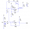
See Fig. 4.3, here. Frequency and duty cycle are independently adjustable, with (ideally) no interaction.
Actually, you don't even need the 555. You can use another section of the comparator in in place of the 555. You might need a couple of extra resistors.
EDIT: below is an example.
Actually, you don't even need the 555. You can use another section of the comparator in in place of the 555. You might need a couple of extra resistors.
EDIT: below is an example.
Attachments
-
 20.5 KB Views: 133
Last edited:
ooOOOoohhh
thanks, i hadn't gotten to that chapter yet, ill look into it
Although i think i need the 555 because im using pin 5 to control the chip with audio, this is probably do-able by other means, but this is probably the simplest way, plus i have them lying around everywhere in case i blow them
thanks, i hadn't gotten to that chapter yet, ill look into it
Although i think i need the 555 because im using pin 5 to control the chip with audio, this is probably do-able by other means, but this is probably the simplest way, plus i have them lying around everywhere in case i blow them

um, I think this means that I need the audio coming in on a capacitor, at 2/3 Vcc, and non-inverting input means... pin 5??summing your DC isolated audio signal with the reference voltage at R7 to the noninverting input.
Did I catch that right?

[EDIT]
oh, this wasn't referencing the 555, so yea, whats the noninverted input?
(time to learn a new chip/concept...)
[EDIT2]
could 1/2 of an LM3900 be substituted for the LM393?
i have one of these laying around
Last edited:
Well, the LM3900 could be used, I suppose. It's a bit on the slow side; GBW is only around 2.5MHz - but you're probably not aiming for high fidelity anyway, right?
To get the PWM portion out of the range of hearing, the base PWM frequency probably needs to be around 22kHz or higher. I can't hear anywhere near that high of a frequency anymore due to exposure to jet aircraft noise and age; but young folks can.
To get the PWM portion out of the range of hearing, the base PWM frequency probably needs to be around 22kHz or higher. I can't hear anywhere near that high of a frequency anymore due to exposure to jet aircraft noise and age; but young folks can.
nope, just need to get it out of audible range, although i think i might have to use a flyback since i doubt the ignition coil off the '67 mustang can go high enoughWell, the LM3900 could be used, I suppose. It's a bit on the slow side; GBW is only around 2.5MHz - but you're probably not aiming for high fidelity anyway, right?
Yea, i can hear the noise coming off of some tube T.V's depending on their type of housing, the big one in our basement gives me a headacheTo get the PWM portion out of the range of hearing, the base PWM frequency probably needs to be around 22kHz or higher. I can't hear anywhere near that high of a frequency anymore due to exposure to jet aircraft noise and age; but young folks can.
and i still don't know what you meant by non inverting input...
Oops, the LM3900 won't work for this - at least not tonight anyway. It's a Norton amplifier, and I haven't worked with those in quite awhile. It has different characteristics than typical modern opamps and I forgot the correct usage offhand - too tired to look it up at the moment.
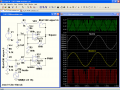
I took Ron's circuit and changed it a bit for use with a TL071/TL072 opamp; a :TL082 or LF353 could also be used. It's simplified a bit, as the incoming audio may need to be buffered.
Tri, the green trace, is the 20kHz triangle wave from C1.
Audio, the white trace, is the incoming audio signal; I just used a 1kHz sine wave. The DC level is blocked by C2, which is perhaps a tad small, but I just wanted the simulation to finish more quickly. As you can see, the audio signal goes above and below 0v by 0.65v/650mV.
Noninv, the yellow trace is the non-inverting (+) input to opamp U2. As you can see, it's now traversing 4.5v, and about the same amplitude as the triangle wave on top. The little "glitches" are due to the feedback from the 1 Meg resistor, which is adding a bit of hysteresis feedback. On the bottom is the PWM output; note that the duty cycle is going from 100% to 0%. I set up the demo to do that deliberately; you wouldn't want that to happen with the actual circuit as it would cause distortion. However, this was just to illustrate that it will in fact go from 0% to 100% PWM.
I took Ron's circuit and changed it a bit for use with a TL071/TL072 opamp; a :TL082 or LF353 could also be used. It's simplified a bit, as the incoming audio may need to be buffered.
Tri, the green trace, is the 20kHz triangle wave from C1.
Audio, the white trace, is the incoming audio signal; I just used a 1kHz sine wave. The DC level is blocked by C2, which is perhaps a tad small, but I just wanted the simulation to finish more quickly. As you can see, the audio signal goes above and below 0v by 0.65v/650mV.
Noninv, the yellow trace is the non-inverting (+) input to opamp U2. As you can see, it's now traversing 4.5v, and about the same amplitude as the triangle wave on top. The little "glitches" are due to the feedback from the 1 Meg resistor, which is adding a bit of hysteresis feedback. On the bottom is the PWM output; note that the duty cycle is going from 100% to 0%. I set up the demo to do that deliberately; you wouldn't want that to happen with the actual circuit as it would cause distortion. However, this was just to illustrate that it will in fact go from 0% to 100% PWM.
Attachments
-
 84.8 KB Views: 132
Those coils weren't meant for this kind of duty. Even if the engine were turning 7,000 RPM, that's less than 500 Hz for the spark on a V8.nope, just need to get it out of audible range, although i think i might have to use a flyback since i doubt the ignition coil off the '67 mustang can go high enough
Now you have to post a photo of the Mustang.
(I had a '65 GT convertible.)
I know and remember that sound.Yea, i can hear the noise coming off of some tube T.V's depending on their type of housing, the big one in our basement gives me a headache
It sucked. My folks told me I was hearing things. I WAS, the $%&*$%$ TV!! The main features of opamps are the inverting (-) input, the non-inverting (+) input, and the output.And i still don't know what you meant by non inverting input...
The inverting input tries to make its' input do what the non-inverting input is doing by adjusting the output.
That probably sounds confusing as the dickens at the moment, but once you start experimenting with opamps and feedback paths, it'll start to make a lot more sense.

OK, so you are replacing two ICs with one IC and adding a lot of resistors. The design I showed is proven, it works well, and is cheap. Think about it. Why the rush to go for something different that could have some unexpected problems. Just because it is different?
Back to the internet then...Oops, the LM3900 won't work for this - at least not tonight anyway. It's a Norton amplifier, and I haven't worked with those in quite awhile. It has different characteristics than typical modern opamps and I forgot the correct usage offhand - too tired to look it up at the moment.
buffered? im familiar with the term as in storing data, but i dont think i understand it in this context.I took Ron's circuit and changed it a bit for use with a TL071/TL072 opamp; a :TL082 or LF353 could also be used. It's simplified a bit, as the incoming audio may need to be buffered.
OK, i get that, but im still a little fuzzy on the concept of the output feeding the input, if i read it correctly then the when the capacitor charge is low, its outputting and charging, when its high it stops charging the capacitor which then dumps into... where? Ground through R1 and VR1, into the output?? i think?Tri, the green trace, is the 20kHz triangle wave from C1.
so id use maybe 30μF and replace the sine wave with my audio input source?Audio, the white trace, is the incoming audio signal; I just used a 1kHz sine wave. The DC level is blocked by C2, which is perhaps a tad small, but I just wanted the simulation to finish more quickly. As you can see, the audio signal goes above and below 0v by 0.65v/650mV.
When did this go from ±mV to 4.5v??Noninv, the yellow trace is the non-inverting (+) input to opamp U2. As you can see, it's now traversing 4.5v, and about the same amplitude as the triangle wave on top.
That word... :GLARE:The little "glitches" are due to the feedback from the 1 Meg resistor, which is adding a bit of hysteresis feedback.
I GET THIS ONE!!On the bottom is the PWM output; note that the duty cycle is going from 100% to 0%. I set up the demo to do that deliberately; you wouldn't want that to happen with the actual circuit as it would cause distortion. However, this was just to illustrate that it will in fact go from 0% to 100% PWM.
So for the project, The base duty cycle and frequency are set by U3 and VR1? and to find them i just measure the pwm out without any audio in? then i can add a constant tone and measure the volume at the plasma using a decibel meter to measure efficiency? or is my entire basis off here?
yea, my mechanical engineer father and I worked that out over dinner one evening, my average teenage sister was appalled by the massive amount of geek emanatingThose coils weren't meant for this kind of duty. Even if the engine were turning 7,000 RPM, that's less than 500 Hz for the spark on a V8.
Had?Now you have to post a photo of the Mustang.
(I had a '65 GT convertible.)
i would post one, but its in the garage covered in junk, hasn't run in years.
If you were to start a cars thread in the off topic i might be tempted to discuss MY mustang though
pretty muchI know and remember that sound.
yea, you could say that, but if i read this right, when the - is greater than the +, the output becomes grounded?The main features of opamps are the inverting (-) input, the non-inverting (+) input, and the output.
The inverting input tries to make its' input do what the non-inverting input is doing by adjusting the output.
That probably sounds confusing as the dickens at the moment, but once you start experimenting with opamps and feedback paths, it'll start to make a lot more sense.
Good point, ill look into both, i plan on messing with the 555 first anyway since i have some, and i dont have any op-amp comparators.OK, so you are replacing two ICs with one IC and adding a lot of resistors. The design I showed is proven, it works well, and is cheap. Think about it. Why the rush to go for something different that could have some unexpected problems. Just because it is different?
Sorry, just realized how long my earlier post was, ill boil it down to this
i would post one, but its in the garage covered in junk, hasn't run in years.
If you were to start a cars thread in the off topic i might be tempted to discuss MY mustang though
and also
So for the project, The base duty cycle and frequency are set by U3 and VR1? and to find them i just measure the pwm out without any audio in? then i can add a constant tone and measure the volume at the plasma using a decibel meter to measure efficiency? or is my entire basis off here?
And Thank you very much for the circuit and the simulation!
buffered? im familiar with the term as in storing data, but i dont think i understand it in this context.I took Ron's circuit and changed it a bit for use with a TL071/TL072 opamp; a :TL082 or LF353 could also be used. It's simplified a bit, as the incoming audio may need to be buffered.
if i read it correctly then the when the capacitor charge is low, its outputting and charging, when its high it stops charging the capacitor which then dumps into... where? through R1 and VR1, into the output?? i think?Tri, the green trace, is the 20kHz triangle wave from C1.
So how exactly does the signal go from the millivolts to 4 volts?Noninv, the yellow trace is the non-inverting (+) input to opamp U2. As you can see, it's now traversing 4.5v, and about the same amplitude as the triangle wave on top.
Had?Now you have to post a photo of the Mustang.
(I had a '65 GT convertible.)
i would post one, but its in the garage covered in junk, hasn't run in years.
If you were to start a cars thread in the off topic i might be tempted to discuss MY mustang though
if i read this right, when the - is greater than the +, the output becomes grounded?The main features of opamps are the inverting (-) input, the non-inverting (+) input, and the output.
The inverting input tries to make its' input do what the non-inverting input is doing by adjusting the output.
That probably sounds confusing as the dickens at the moment, but once you start experimenting with opamps and feedback paths, it'll start to make a lot more sense.
and also
So for the project, The base duty cycle and frequency are set by U3 and VR1? and to find them i just measure the pwm out without any audio in? then i can add a constant tone and measure the volume at the plasma using a decibel meter to measure efficiency? or is my entire basis off here?
And Thank you very much for the circuit and the simulation!
OK.Sorry, just realized how long my earlier post was, ill boil it down to this
In analog terms, it means a very high-impedance input and a low-impedance output. Think of it in terms as a current amplifier.buffered? im familiar with the term as in storing data, but i dont think i understand it in this context.
C1 is simply a timing capacitor. It's charged and discharged by the resistor connected to the output of the opamp. It doesn't "dump into" anywhere. It's used as a voltage reference at the inverting input of U1b.if i read it correctly then the when the capacitor charge is low, its outputting and charging, when its high it stops charging the capacitor which then dumps into... where? through R1 and VR1, into the output?? i think?
C2 blocks the DC level. The R9/U3/R10 network establishes the new DC level.So how exactly does the signal go from the millivolts to 4 volts?
Capacitors block DC, and pass the effects of AC. This is a very important concept to understand.
re: '65 Mustang GT convertible:
Yep, I had one. Bought it for $75. Rebuilt the engine and transmission, and drove it for over a year. Sold it to my Marine Recruiter for $200 right before I shipped to Boot Camp. The rear end went out on him two weeks later. He swapped the original rear end for one from a T-bird, and later sold it to another Marine Recruiter. I'd like to think it's still running around somewhere, but that's practically beyond hope now.Had?
Re: photo of the '67:
Show some interest in that car, young man. Clear the stuff off of it. Push it out of the garage and give it it a bath, and get it back inside the same day. Get your Dad interested in fixing all the stuff that's wrong with it. If it's rusting, you have to stop the rust right now; otherwise it'll soon be ready for the junk yard. The sooner you start preserving it, the less the restoration will cost.I would post one, but its in the garage covered in junk, hasn't run in years.
I don't have one anymore; it's been gone a long time.If you were to start a cars thread in the off topic i might be tempted to discuss MY mustang though
However, since you DO have one, you should start a thread in the off-topic forum, and you should get your keister to work on that car.
Not quite.If i read this right, when the - is greater than the +, the output becomes grounded?
The inverting input tries to make its' input do what the non-inverting input is doing by adjusting the output.
It's that simple. That's why you can adjust the feedback path of opamps to get varying amounts of amplification. However, when you're dealing with higher speed circuits, bandwidth limitations will "bite" you.
The base frequency is set by C1, R1, and VR1. R1 is there just in case you adjust VR1 too low, as the pot could otherwise get fried.and also
So for the project, The base duty cycle and frequency are set by U3 and VR1?
The base duty cycle is set by R9, R10 and U3. Ideally, it will be around 50% with no audio input. This could be simplified by an RC integrator network from C1; then these components could go away.
To find the base frequency, you'd measure the triangle wave on the top of C1.and to find them i just measure the pwm out without any audio in?
To find the PWM %, you could simply look at the output of U1b, and see what the actual duty cycle is.
You're a bit ahead of the game, as all I've posted is a PWM output of low current; it's not really suitable for driving a transistor or MOSFET at the moment.Then i can add a constant tone and measure the volume at the plasma using a decibel meter to measure efficiency? or is my entire basis off here?
That's sort of what we do here.And Thank you very much for the circuit and the simulation!
Bill, I don't think of 3 as being a "lot of resistors".OK, so you are replacing two ICs with one IC and adding a lot of resistors. The design I showed is proven, it works well, and is cheap. Think about it. Why the rush to go for something different that could have some unexpected problems. Just because it is different?
As for it being different, it is undeniably that, but I'll wager that the oscillator portion of the circuit I posted (using various comparators or op amps) was around before the 555 was even a gleam in Hans Camenzind's eye, so it's not exactly untried and unproven.
Having said all that, I don't have a preference for the one I posted over the 555. I was just offering it as an alternative. Perhaps someone might have an LM393 or 339 lying around, or, as Wookie suggested, a TL072 or some similar op amp with relatively high slew rate, but no 555.
Still not getting it, ill have to look into it.In analog terms, it means a very high-impedance input and a low-impedance output. Think of it in terms as a current amplifier.
So, does the output actually put out positive voltage, because i was seeing things that say that it goes from disconnected to grounded, im sure this is simple but its not clickingC1 is simply a timing capacitor. It's charged and discharged by the resistor connected to the output of the opamp. It doesn't "dump into" anywhere. It's used as a voltage reference at the inverting input of U1b.
http://www.sullivan-county.com/ele/vc_files/Comparax.gif
I get that they block DC and pass AC, but why doesen't it just make a 4.5V wave ±700mV?C2 blocks the DC level. The R9/U3/R10 network establishes the new DC level.
Capacitors block DC, and pass the effects of AC. This is a very important concept to understand.
So it can both sink and output voltage???Not quite.
The inverting input tries to make its' input do what the non-inverting input is doing by adjusting the output.
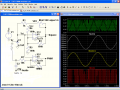
like the attachment?This could be simplified by an RC integrator network from C1; then these components could go away.
i dont think thats right as it looks like it would just cause interference
I see U1, where is U1b?To find the PWM %, you could simply look at the output of U1b, and see what the actual duty cycle is.
then where DOES it go?You're a bit ahead of the game, as all I've posted is a PWM output of low current; it's not really suitable for driving a transistor or MOSFET at the moment.
i was planning on using a PNP to drive a larger transistor which would drive a MOSFET
yes, but you don't HAVE toThat's sort of what we do here.
Attachments
-
 82.4 KB Views: 41
Its not mine, and its not "rolling" anywhere soon, theres another mustang and 2 feet of snow right outside the driveway. it should be easy to roll in the spring though, most of the engine isnt in itre: '65 Mustang GT convertible:
Yep, I had one. Bought it for $75. Rebuilt the engine and transmission, and drove it for over a year. Sold it to my Marine Recruiter for $200 right before I shipped to Boot Camp. The rear end went out on him two weeks later. He swapped the original rear end for one from a T-bird, and later sold it to another Marine Recruiter. I'd like to think it's still running around somewhere, but that's practically beyond hope now.
Re: photo of the '67:
Show some interest in that car, young man. Clear the stuff off of it. Push it out of the garage and give it it a bath, and get it back inside the same day. Get your Dad interested in fixing all the stuff that's wrong with it. If it's rusting, you have to stop the rust right now; otherwise it'll soon be ready for the junk yard. The sooner you start preserving it, the less the restoration will cost.
I don't have one anymore; it's been gone a long time.
However, since you DO have one, you should start a thread in the off-topic forum, and you should get your keister to work on that car.
dont worry, its being taken care of, its nice and dry and im pretty sure rust free. But the engine needs completley rebuilt, and we dont have the money right now, specially with my dads company moving soon.
He wants to sell it and just buy another, i wont let him, id rather restore it
MY mustang is a 1990 gt convertable
(not as cool, but a good first car
)it needs a bit of work, new top hydraulics and i need to put the radio i got in it,
and a paint job
and new tires
and i want a new hood
but it runs like a charm, currently in hibernation for the winter
OK. Line-level audio is a high-impedance voltage source. If you put much of a load on it at all, you won't see much (if any) signal.Still not getting it, ill have to look into it.Originally Posted by SgtWookie
In analog terms, it means a very high-impedance input and a low-impedance output. Think of it in terms as a current amplifier.
Operational amplifiers, particularly those with JFET inputs like the TL0xx series opamps, have a very high input impedance, on the order of a trillion Ohms (1,000,000 megohms.) This means that even a high-impedance source (like line-level audio) sees very little loading effect. The output side of the TL0xx series opamps can source or sink a fair amount of current (around 6mA) before getting excessively loaded.
Opamps' outputs can source and/or sink current. Typical comparators that hobbyists use(LM339, LM393, etc) have open-collector outputs, which can only sink current; with these types, a pull-up resistor is used. There ARE comparators that can both source and sink current.So, does the output actually put out positive voltage, because i was seeing things that say that it goes from disconnected to grounded, im sure this is simple but its not clickingC1 is simply a timing capacitor. It's charged and discharged by the resistor connected to the output of the opamp. It doesn't "dump into" anywhere. It's used as a voltage reference at the inverting input of U1b.
http://www.sullivan-county.com/ele/v...s/Comparax.gif
Capacitors block DC, and pass the effects of AC. This is a very important concept to understand.C2 blocks the DC level. The R9/U3/R10 network establishes the new DC level.
I get that they block DC and pass AC, but why doesen't it just make a 4.5V wave ±700mV?
Operational amplifiers can both sink and source current, yes. Some comparators can both sink and source current, too - but the most common ones (like LM339, LM393, LM2903, etc) have open-collector outputs and can only sink current.Did you look at waveforms V(audio) and V(noninv)? They are basically the same, except V(noninv) is ~4.5v higher than V(audio).
So it can both sink and output voltage???Not quite.
The inverting input tries to make its' input do what the non-inverting input is doing by adjusting the output.
Depends on how it's done. All it needs to do is to establish a voltage level that's centered on the triangle wave from C1.like the attachment?This could be simplified by an RC integrator network from C1; then these components could go away.
i dont think thats right as it looks like it would just cause interference
Sorry, U1 should have been labeled U1a, and U2 should have been labeled U1b, as both of those opamps are in one IC. For now, U2 is what I referred to as U1a.I see U1, where is U1b?To find the PWM %, you could simply look at the output of U1b, and see what the actual duty cycle is.
Right now, it's not going anywhere - it's just present at the point labeled PWM.then where DOES it go?You're a bit ahead of the game, as all I've posted is a PWM output of low current; it's not really suitable for driving a transistor or MOSFET at the moment.
I guess you'll need to 'splain that one.I was planning on using a PNP to drive a larger transistor which would drive a MOSFET
I know - besides, the pay is lousy.yes, but you don't HAVE toThat's sort of what we do here.
so, putting a load on it makes it go away, but trillion ohms is fine?OK. Line-level audio is a high-impedance voltage source. If you put much of a load on it at all, you won't see much (if any) signal.
Operational amplifiers, particularly those with JFET inputs like the TL0xx series opamps, have a very high input impedance, on the order of a trillion Ohms (1,000,000 megohms.) This means that even a high-impedance source (like line-level audio) sees very little loading effect. The output side of the TL0xx series opamps can source or sink a fair amount of current (around 6mA) before getting excessively loaded.
i dont think im getting the word impediance, my mind is going

Right now
Now this makes sense, thanksOperational amplifiers can both sink and source current, yes. Some comparators can both sink and source current, too - but the most common ones (like LM339, LM393, LM2903, etc) have open-collector outputs and can only sink current.
Depends on how it's done. All it needs to do is to establish a voltage level that's centered on the triangle wave from C1.
Sorry, U1 should have been labeled U1a, and U2 should have been labeled U1b, as both of those opamps are in one IC. For now, U2 is what I referred to as U1a.
*sigh...Right now, it's not going anywhere - it's just present at the point labeled PWM.
Where CAN it go?
Take the PWM, put it to a small NPN, which goes to the base of a PNP, which pulls the MOSFET to ground...I guess you'll need to 'splain that one.
though thinking about it i shouldn't need a PNP at all, this was intended to reverse the output of a 555, which this circuit doesn't use...
You get paid in the satisfaction of knowing that you're teaching something to someone like me who will just go use it for something dangerous and uselessI know - besides, the pay is lousy.
and for this i thank you





