555pwm, same duty cycle, varying frequency & vica versa

SgtWookie

Joined Jul 17, 2007
22,230
so, putting a load on it makes it go away, but trillion ohms is fine?
i dont think im getting the word impediance, my mind is going

Right now
Your head asploded? :)
Here's a link explaining impedance: http://en.wikipedia.org/wiki/Electrical_impedance
To keep things simple, let's just say for now that impedance is very similar to resistance, but for AC signals.

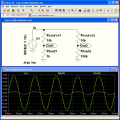
Here is a simulation of what happens to an input signal when the load is relatively heavy vs relatively light:


The input signal is a 1kHz sine wave that is 2v p-p.
For both outputs, the resistance of the source is 10k Ohms.
On the left, the load resistance is 1k Ohms, and on the right, 100k Ohms.
Out1 and Out2 are measured at the junctions of the resistors. Basically what we have here is a pair of resistive dividers.

V(Out1) = In / (Rsource1+Rload1)/Rload1
V(Out1) = In / (10k+1k)/1k
V(Out1) = In / 11 ; so if In=1v, then Out1 ~= 90.9mV

V(Out2) = In / (Rsource2+Rload2)/Rload2
V(Out2) = In / (10k+100k)/100k
V(Out2) = In / 1.1; so if In=1v, then Out2 ~= 909mV

Now imagine if Rload2 were 1,000,000 million Ohms, which is the input resistance of the TL0xx series opamps.
The load is so small compared to the source resistance, that the output would be reduced by a very, very small amount:
V(Vut3) = In / 1.00000001

re: PWM out
*sigh...
Where CAN it go?
The amplitude of the output is right, but it would need to go through a current amplifier, like a MOSFET gate driver IC, in order to be able to switch the MOSFET on and off quickly enough.
 

Attachments

Thread Starter

magnet18

Joined Dec 22, 2010
1,227
Your head asploded? :)
Here's a link explaining impedance: http://en.wikipedia.org/wiki/Electrical_impedance
To keep things simple, let's just say for now that impedance is very similar to resistance, but for AC signals.

Here is a simulation of what happens to an input signal when the load is relatively heavy vs relatively light:

The input signal is a 1kHz sine wave that is 2v p-p.
For both outputs, the resistance of the source is 10k Ohms.
On the left, the load resistance is 1k Ohms, and on the right, 100k Ohms.
Out1 and Out2 are measured at the junctions of the resistors. Basically what we have here is a pair of resistive dividers.

V(Out1) = In / (Rsource1+Rload1)/Rload1
V(Out1) = In / (10k+1k)/1k
V(Out1) = In / 11 ; so if In=1v, then Out1 ~= 90.9mV

V(Out2) = In / (Rsource2+Rload2)/Rload2
V(Out2) = In / (10k+100k)/100k
V(Out2) = In / 1.1; so if In=1v, then Out2 ~= 909mV

Now imagine if Rload2 were 1,000,000 million Ohms, which is the input resistance of the TL0xx series opamps.
The load is so small compared to the source resistance, that the output would be reduced by a very, very small amount:
V(Vut3) = In / 1.00000001
I get it now, my head un-asploded :)

your simulation explained it for me :)

its not the resistance in the circuit (ignore my poor wording, hopefully you get what I'm saying) its the resistance behind it, like the "bottom" part of a voltage divider :)

My intuition tells me it might have something to do with the electrons "piling up" against the resistance, but i have no idea if this is correct...

re: PWM out


The amplitude of the output is right, but it would need to go through a current amplifier, like a MOSFET gate driver IC, in order to be able to switch the MOSFET on and off quickly enough.
Is this like another op-amp?

theres still just one thing I don't get, I know capacitors block DC and pass AC, but why doesen't it just make a 4.5V wave ±700mV? why does it change the voltage so much?
 

Thread Starter

magnet18

Joined Dec 22, 2010
1,227
Alright, I think I get the MOSFET driver, but theres still just one thing I don't get, I know capacitors block DC and pass AC, but why doesen't it just make a 4.5V wave ±700mV? why does it change the voltage so much?
 

SgtWookie

Joined Jul 17, 2007
22,230
Alright, I think I get the MOSFET driver, but theres still just one thing I don't get, I know capacitors block DC and pass AC, but why doesen't it just make a 4.5V wave ±700mV? why does it change the voltage so much?
The capacitor doesn't "change" the voltage; it simply isolates the DC voltage levels on either side of the cap. The effects of the AC signal are still passed through the capacitor.

As long as the voltage difference between the leads of the capacitor does not exceed the caps' voltage rating, the DC voltage difference can be purely arbitrary.

Many single-supply circuits depend on this very concept.

In a previous circuit I posted, the input signal is a 1kHz sine wave that varied from -0.65v to 0.65v; it was centered on 0v; so the average voltage was zero. There is an 0.22uF capacitor that couples the AC signal to a DC level that averages 4.5v due to biasing with a resistor network. So, the average DC level on that side of the cap is still 4.5v, but there are excursions up to 0.65v above and 0.65v below the 4.5v average level.
 

Thread Starter

magnet18

Joined Dec 22, 2010
1,227
OK, I did understand it, i just thought i didnt because i thought that the amplitude of the noninv wave was grreater than that of the sine wave, apparently i forgot how to convert mV to V, sorry :rolleyes:

Thanks for all the helps, i think i understand the circuit now :)
 

Thread Starter

magnet18

Joined Dec 22, 2010
1,227
Just wanting to make sure before i buy anything (These are pretty expensive!), is this an appropriate gate driver?
or does a better (cheaper) one come to mind?
 

SgtWookie

Joined Jul 17, 2007
22,230
The FAN7387 gate driver you linked to is pretty spiffy with it's own charge pump, but that's more for H-bridges, synchronous rectifiers or push-pull SMPS designs; it's both a high and low side driver with a charge pump in one package.

You just need a single low-side driver. You might look at a TC429, TC4420, TC4422 or similar. Those are made by Microchip, and should be pretty inexpensive.
 

SgtWookie

Joined Jul 17, 2007
22,230
You could try using 2N2907 and 2N2222 transistors as emitter followers on the output to drive the gate. It won't be as good as a dedicated MOSFET gate driver IC, but the price may be more agreeable to you.

You might also use a 555 timer as a Schmitt trigger.
 

Thread Starter

magnet18

Joined Dec 22, 2010
1,227
Wookie, Im trying to re-create your schemtic in LT spice, I couldn't find a TL017, Is it the LT1017, or is it some other number, or is it a custom part?

And how would i put that mosfet driver and the flyback in?
Can spice even handle a flyback?
 

SgtWookie

Joined Jul 17, 2007
22,230
Yes, you have to add opamps that LTSpice doesn't come with.

I've attached opamps.zip - there are a number of files in there.

Copy all the .asy files to \Program Files\LTC\SwitcherCad\lib\sym\Opamps
Copy the other files to \Program Files\LTC\SwitcherCad\lib\sub
Close and re-start LTSpice, and you should see them in the Add Component dialog window when you go to add an opamp.
 

Attachments

Ron H

Joined Apr 14, 2005
7,063
I just place an opamp2, change its name to the name of the subckt, and place a .lib subckt.sub (e.g., .lib TL071.sub) directive on the schematic. Of course, you have to know what subckts you have, because they don't show up in the Select Component Symbol window.
 

SgtWookie

Joined Jul 17, 2007
22,230
One of these days, I'm going to merge all of my downloaded opamp .subckt's into one .lib file, and then just have one "misc" opamp where I'll be able to select any .subckt from a scrolling window via right-clicking on the icon and selecting it from the scrolling window you get if the .lib or .sub is declared and there is more than one .subckt in the file, and you've previously entered a defined .subckt in the SpiceModel field.
 

Ron H

Joined Apr 14, 2005
7,063
One of these days, I'm going to merge all of my downloaded opamp .subckt's into one .lib file, and then just have one "misc" opamp where I'll be able to select any .subckt from a scrolling window via right-clicking on the icon and selecting it from the scrolling window you get if the .lib or .sub is declared and there is more than one .subckt in the file, and you've previously entered a defined .subckt in the SpiceModel field.
That sounds interesting. I tried it with a file I have called LM78XX.lib. I placed .lib LM78XX.lib on the schematic, and I placed a DIP3 symbol (that I made years ago), and entered "LM7812" in the SpiceModel field (LM7812 is one of the subckts in the file). When I right click on the symbol, I don't get a scrolling window. Did I miss something?
 

SgtWookie

Joined Jul 17, 2007
22,230
Yes, I've been playing around with it a bit lately.

Unzip the attached into the appropriate Switchercad subdirectories.

Since I don't fiddle with tubes/valves much anymore, I just put R_triode.asc in the \sym\misc subdirectory.

Then open Triode_test.asc.

Right-click on the 12AX7 tube/valve.
Double-click on the right end of the SpiceModel text box; note that it'll change to a DownArrow, which means that it's now scrollable.

You can either use the arrow keys to navigate up and down through the list of tubes/valves, or you can click on the arrow to get a "page view" list that you can click on to select a model.

Charles Rydel uploaded a .lib file to the Yahoo! LTSpice Users' Group with various triodes, tetrodes and pentode models in it. I separated them into three different libraries, and made separate .asy files from the supplied LTSpice symbols for the different libraries. They have the ModelFile field filled out with their respective names. Apparently, you can also place a collection of .subckts in a file and call that out in the SpiceModel field, and have an individual .subckt called out in the Name field.

Wouldn't have made sense to keep triodes, tetrodes and pentodes in the same library when the symbol files wouldn't have the connections to support the models.
 

Attachments

Last edited:

Thread Starter

magnet18

Joined Dec 22, 2010
1,227
Alright, thanks :)
Any advice with using spice/any good tutorials you know of?
[edit]
I got all the files in there correctly, had a slightly different path but I managed, thanks :)
 
Last edited:

Thread Starter

magnet18

Joined Dec 22, 2010
1,227
So do I use the TLV247xA and just edit the name?
aaaannd im sounding like a horrible noob but how do you get a potentiometer?
 
Last edited:

Ron H

Joined Apr 14, 2005
7,063
Wookie, your triode example works for me, but I can't figure out how to do the same thing with a different symbol and .lib file.
 

SgtWookie

Joined Jul 17, 2007
22,230
So do I use the TLV247xA and just edit the name?
No, there's a TL07x in the opamps.zip I uploaded; just use that one.

aaaannd im sounding like a horrible noob but how do you get a potentiometer?
I've attached pot.zip.

Put the .sub file in Program Files\SwitcherCad\lib\sub
Put the .sym file in Program Files\SwitcherCad\lib\asy

If LTSpice is open already, it won't "see" pot.sym until you close and re-run LTSpice.
 

Attachments

Top