555 timer trigger latch

Thread Starter

readym

Joined Jul 19, 2011
13
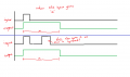
I want to be have a 555 timer that can only be triggered once the discharge cycle is over.

Meaning that i want to trigger the timer, allow it to enable output HIGH (charge cycle) and then on discharge cycle output will be LOW, but trigger must not be allowed to trigger timer till discharge cycle is over.

I know that if you hold RESET (pin 4) LOW, trigger (pin 2) will not be allowed till pin 4 is HIGH again.

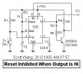
I want to design a circuit to hold RESET LOW till discharge cycle is over, then trigger is allowed.
 

Thread Starter

readym

Joined Jul 19, 2011
13
On my attached drawing i have left a block labeled "Circuit to NOT allow trigger till discharge circuit is over", that's where im not sure what to add to not allow the switch to trigger pin2 till discharge cycle is over.

Please help...
 

Attachments

Sparky49

Joined Jul 16, 2011
833
Bearing in mind I'm not very experienced with electronics - here's my idea.

I think putting a small capacitor in series with the trigger pin, with a parallel resistor. This should mean the Vcc decays below the voltage needed to trigger the 555, the parallel resistor would help the capacitor discharge.

I'd wait until someone more experienced replys though, unless you've got some spare components and a breadboard!:D
 

Thread Starter

readym

Joined Jul 19, 2011
13
Thanks for the reply, i understand what you mean that would only decay the time to trigger once the trigger button is pressed. but what I want to do is when capacitor on pin6 is discharging,and trigger button is pushed then timer can't trigger till discharge is done, then trigger is allowed.
 

Sparky49

Joined Jul 16, 2011
833
It's made it worse!:D

I've altered the image slightly. At the end the output goes high again - but with no change of input - is this correct? 'Cause it looks like this is showing astable, whilst the schematic shows monostable config.

Is the wave 'output 2' what you're wanting?
 

Attachments

Last edited:

Thread Starter

readym

Joined Jul 19, 2011
13
I only put that part high to show end of cycle, but output 2 looks good. t1 is charge cycle and t2 is discharge cycle. trigger must not be allowed during discharge cycle.
 

Sparky49

Joined Jul 16, 2011
833
I haven't got any exact plans for a schematic, but have you considered linking th output of the 555 timer (call it timer x) to trigger another (timer y)?

When the output of the x goes low, it triggers y. This then 'cuts off' the reset for x, via a transistor, until y itself goes low. Then the reset for x is restored and can be re-triggered.

I don't think I've explained it very well, but perhaps you can make out what I'm suggesting?

BTW, what is this for?
 

Thread Starter

readym

Joined Jul 19, 2011
13
I think I understand what you mean I changed the schematic, do you mean having two monostable timers to trigger eachother? But then how do I disable the trigger function on X using Y as the manipulator?
 

Attachments

Thread Starter

readym

Joined Jul 19, 2011
13
That would work, the design could become bulky thou, is there a way i could use a transistor instead of a relay?
 

Sparky49

Joined Jul 16, 2011
833
Not too bulky - a PCB relay would be shorter than the two 555s or a 556.

Consider something along the lines of a RS low profile SPDT relay.

I'll have a look through my (slightly) outdated RS catalogue, for a specific part number for you.:)
 

Sparky49

Joined Jul 16, 2011
833
Hi again

The stock numbers are as follows;

6V 12A - 476-707
12V 12A - 476-690
24V 12A - 476-719

It's up to you what you choose. These are only 29x12x15mm, so quite small.


Let us know how you got on - I'm wanting pictures.:D
 
I know this is way too late but the 555 does exactly what you want all on its own, once the trigger has been activated all other triggers are ignored until the end of the timing sequence.

If I understand you correctly that exactly what you require, you don't need any more circuitry. Just look up the pin descriptions for the 555 and how it works.
 

ScottWang

Joined Aug 23, 2012
7,397
If your point is Reset Inhibited during Pin 3 output High, then you just need to add a inverter from pin 3 to the reset pin 4, I used the NPN transistor to be that inverter.

If you want to control the reset pin, then you can cut off the ctrl point, and connecting R3 to the place where is your control signal.


If you want to detecting the voltage of pin 6 more precisely, then you can add op amp as LM358 to replace the NPN transistor, and cut off the ctrl point, and connecting R3 to Pin 6.
 

Attachments

Last edited:
Top