555 Timer - Set Duty Cycle

Thread Starter

pcon2009

Joined Aug 5, 2012
18
I had a post before asking a whole host of questions about a project I am working on, but I am changing things little by little so I thought it would be best to start fresh with a new thread and describe an issue that seems to be at the root of the problem.

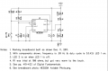
I am using a 555 Timer IC to alternatly flash two LEDs. I am looking for an approximately 50% duty cycle at something around 10-20Hz. I used an online calculator to determine that an R1 value of 1kΩ and an R2 of 15kΩ with a 3.3μF C1 capacitor should give me something like 16Hz.

Yet, it seems that no matter what I do to try and change things up the flash rate either exists as a strobing effect that is too fast for what I want, or both LEDs in the circuit don't alternate and stay steady.

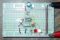
The circuit I am using is below:


I just don't understand what is going on here. Can someone help me determine what the correct resistor/capacitor values should be? If I can get this step figured out I can move on to the next issue (which, if anyone is curious, the LEDs are high-power 3W so I know I can't drive them with the 555 and need to use transistors to amplify. Again, though this is another issue that I will move onto later AFTER I get the first step figured out.)

Thanks!
 

Wendy

Joined Mar 24, 2008
23,415
The math is basic and works, though some of the values are inconvenient in the end.

Bill's Index

My Cookbook


I already have a specific circuit do to exactly what you are wanting though. As an added bonus it is extra efficient, it will suck the batteries completely dry before it dies.

High Power LED Flasher

Completed Projects Index

If you want to discuss how to do it with a straight multivibrator I would be glad to show you how. The key is to get R1 as low as you can safely go (say ≈ 1KΩ) and R2 as high as it can go, this will create a 50% duty cycle. From there it is the cap, you should be able to do this with 10µF to 100µF.

A totally different circuit I am quite fond of will adjust duty cycle 0-100% while keeping the base frequency rock steady.

 
Last edited:

MrChips

Joined Oct 2, 2009
30,706
If you look at the formula for Duty Cycle that Bill has shown,
for 50% duty cycle you need to make R2 large relative to R1.

For simplicity sake, let us choose R1 = 2kΩ and R2 = 10kΩ

Duty Cycle = (R1 + R2)/(R1 + 2R2)
Duty Cycle = (2k + 10k)/(2k + 20k) = 12k/22k = 0.55

Now to find C1

f = 1.44/(R1 + 2R2)C1
C1 = 1.44/(22k x 20) for f = 20Hz
C1 = 3.3μF

If you wish to fine tune the frequency, adjust R2 only.
For course adjustment of the frequency adjust C1 only.
 

Thread Starter

pcon2009

Joined Aug 5, 2012
18
Thanks for the quick responses!

First off, Bill, I would like to continue in the direction I am currently going. While I really appreciate the fact that you have solved this once already, and I am not tryign to reinvent the wheel, but I would like to keep the circuitry a bit simpler. When it comes to this kind of electronics work, I am pretty much a noob, so the main goal here is to work through the problem so I understand what I did and why it works and what its doing. The learning is more a goal than the functional end result, so I am going to try and stick with this direction for now.

Second, using the math you have both provided makes perfect sense - however, the issue I am having doesn't seem to be with my math because as I have mentioned I have adjusted for several different things and attempted to recreate different duty cycles, different frequencies, etc and the end result always seems to be either two steady lights or an extremely fast strobe (too fast to really distinguish - and I think only one LED is actually strobes, the other stays constant). Can either of you/anyone else provide a couple of possible causes that adjusting my resistor and capacitor values doesn't seem to effect the actual flash rates? Are there some common mistakes I might be able to look for here? I am just kind of at a loss for where to go from here.
 

MrChips

Joined Oct 2, 2009
30,706
Maybe you have your circuit wired incorrectly.
Maybe you forgot to put a 10μF capacitor across Vcc and GND.
What is the part number on your 555?
If the 555 is a regular LM555 or NE555 type and not CMOS, don't make R1 lower than 2kΩ.
 

Wendy

Joined Mar 24, 2008
23,415
In that case keep the currents under 200ma, as that is all the 555 can handle. This is not a spec you can push.

As is, the 555 will get hot, maybe very hot.
 

tracecom

Joined Apr 16, 2010
3,944
Here's my version that works, along with the data to make rate changes. For 10 Hz, change C1 from 100 μF to 10 μF, and leave everything else the same as shown in my schematic. (The switch is a reset switch, which you may omit if you don't need it.) Don't neglect the decoupling cap across the power pins; power supply noise could be your problem.
 

Attachments

Last edited:

THE_RB

Joined Feb 11, 2008
5,438
I generally prefer not to use the discharge pin, but to runs the oscillator from the pin3 output pin through a resistor. That will give you a duty cycle close to 50% from the start.

If you want better control of duty cycle you use the pin3 oscillator technique and add a pot and two diodes, that will give you an adjustable duty range between about 5% to 95%.


Google showed another circuit for 50% duty that i had not seen before, this one from some National app notes;
 
Top