 Facebook
 Google
 GitHub
 Linkedin
Hi,
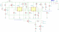
some time ago I designed a circuit which is supposed to generate a short pulse (about 1 ms) upon pressing a tactile switch. In addition, the pause between two successive pulses should be about 2 seconds. I came up with the circuit attached, using one 555 (U2) to generate the pulse and a second
555 (U1) to hold the trigger of the first 555 low for about two seconds. Maybe there are more optimal solutions for that (I'm pretty sure there are) but
the circuit worked as expected when I built it up using THT components (on a PCB).
However, I wanted to get more experienced with SMD soldering. So I decided to create an SMD version of it which is based on the same
circuit.
After I completed the SMD version, it showed some unexpected behaviour in terms of the pulse width generated by U2. Instead
of having a pulse width within the theoretical limits of about 0.5 ms and 1.6 ms (depending on how RV1 is adjusted), I get a pulse width
of about 6.5 ms - no matter how I adjust the pot RV1. Since the timing of U1 is working as expected I suspected that it may be
a problem with U2 or the components connected to it.
I then measured some voltages in the THT and the SMD version and I came up with the following roughly equal measurements for both versions:
VCC: 6.2 V
CV: 4.1 V
So, these values should be fine.
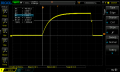
In addition I had a look at the charging curve of cap C9 and there I noticed the significant difference between the two
circuit versions: in the THT version the cap charges up to roughly 66% and then discharges again as expected after about 1 ms (see,
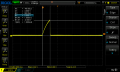
Cap_Charge_THT.png). But in the SMD version the cap seems to get fully charged. And after a while the cap gets discharged a bit (after about 6.5 ms).
It then seems to charge up again for a short period and after reaching the threshold voltage, it discharges completely (see
Cap_Charge_SMD.png).
So to me it seems like the 555 U1 is not detecting correctly the point where the cap is charged above the threshold voltage.
For your information - the timer chips used:
THT: TLC551CP
SMD: TLC555QDRQ1
And as a side note: at first I suspected that there might be a problem with R2 and/or RV1. Hence, I also measured the resistance over them
and it seems to be fine (between 470 and 1470, depending on the settings on RV1). The charging curve of the cap also changes as expected
when adjusting RV1.
Maybe it's some difference between the two timer chips. But I can't see a hint in the datasheets.
Does someone have an explanation for that behaviour I see? It's not an important circuit for me since I'm a beginner and I'm still
learning. But it would be good to understand what's going on in the SMD version.
Best,
Michael
some time ago I designed a circuit which is supposed to generate a short pulse (about 1 ms) upon pressing a tactile switch. In addition, the pause between two successive pulses should be about 2 seconds. I came up with the circuit attached, using one 555 (U2) to generate the pulse and a second
555 (U1) to hold the trigger of the first 555 low for about two seconds. Maybe there are more optimal solutions for that (I'm pretty sure there are) but
the circuit worked as expected when I built it up using THT components (on a PCB).
However, I wanted to get more experienced with SMD soldering. So I decided to create an SMD version of it which is based on the same
circuit.
After I completed the SMD version, it showed some unexpected behaviour in terms of the pulse width generated by U2. Instead
of having a pulse width within the theoretical limits of about 0.5 ms and 1.6 ms (depending on how RV1 is adjusted), I get a pulse width
of about 6.5 ms - no matter how I adjust the pot RV1. Since the timing of U1 is working as expected I suspected that it may be
a problem with U2 or the components connected to it.
I then measured some voltages in the THT and the SMD version and I came up with the following roughly equal measurements for both versions:
VCC: 6.2 V
CV: 4.1 V
So, these values should be fine.
In addition I had a look at the charging curve of cap C9 and there I noticed the significant difference between the two
circuit versions: in the THT version the cap charges up to roughly 66% and then discharges again as expected after about 1 ms (see,
Cap_Charge_THT.png). But in the SMD version the cap seems to get fully charged. And after a while the cap gets discharged a bit (after about 6.5 ms).
It then seems to charge up again for a short period and after reaching the threshold voltage, it discharges completely (see
Cap_Charge_SMD.png).
So to me it seems like the 555 U1 is not detecting correctly the point where the cap is charged above the threshold voltage.
For your information - the timer chips used:
THT: TLC551CP
SMD: TLC555QDRQ1
And as a side note: at first I suspected that there might be a problem with R2 and/or RV1. Hence, I also measured the resistance over them
and it seems to be fine (between 470 and 1470, depending on the settings on RV1). The charging curve of the cap also changes as expected
when adjusting RV1.
Maybe it's some difference between the two timer chips. But I can't see a hint in the datasheets.
Does someone have an explanation for that behaviour I see? It's not an important circuit for me since I'm a beginner and I'm still
learning. But it would be good to understand what's going on in the SMD version.
Best,
Michael
Attachments
-
 147.1 KB Views: 20
 -
 37.9 KB Views: 17
 -
 36.5 KB Views: 9


