Pulse Width Modulation using 555 timer

Thread Starter

AnaCostea

Joined May 14, 2019
1
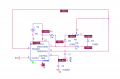
Hey hey! I have a project in ORCAD in which I have to design a PWM with the following parameters: f=15000 Hz, amp. of PWM between 3 and 6 V and duty cycle between 40 and 70%. I am not very good with electronics, so I found a guy on youtube with a video with adjusting the duty cycle of a 555 timer without changing the frequency.I designed the circuit, entered the values he calculated to see how this works, run the simulation and I have nothing at output... I could use some advice about this.
 

Attachments

kumar aman

Joined May 9, 2019
3
i am implementing a pwm using 555, and in circuit diagram, there are two diodes, can any one tell, why diodes are used, and whether this circuit can be made without using diodes in the first place.
 

LesJones

Joined Jan 8, 2017
4,190
It would be a GREAT help if you provides the schematic of the circuit you are building. As you have provided no information a wild guess is that one select the charge path and the other the discharge path.

Les.
 

jpanhalt

Joined Jan 18, 2008
11,087
i am implementing a pwm using 555, and in circuit diagram, there are two diodes, can any one tell, why diodes are used, and whether this circuit can be made without using diodes in the first place.
This old application note describes it: http://www.sophphx.caltech.edu/Physics_5/Data_sheets/555appnote.pdf

The whole note is interesting, but the steering diode discussion starts about page 4.

Yes, it can be made without diodes. In the usual configuration described in datasheets, that limits the duty cycle to more than 50%.
 
Top