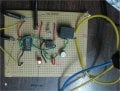
555 timer based water level controller

Thread Starter

rudh89

Joined Jul 18, 2011
3
Hi, I am trying to develop the water level controller shown in this link, "http://kitsnspares.com/admin/pdffiles/simple%20water%20indicator.pdf". The 555 timer as I know is supposed to maintain the previous output state when inputs at pin 6 and 2 are 0 and 1 respectively. But for some reason the output does not maintain its previous state and instead changes state when pin 6 and 2 are given 0 and 1. I have been trying to figure out the problem for the past 2 days and have not succeeded yet. Please please help....
 

Thread Starter

rudh89

Joined Jul 18, 2011
3
I have labelled some of the points slightly hard to figure out, the rest can be found from the circuit in the website. Like i said, what seems to be happening is that the output of 555 changes its state when the input at 6 and 2 is 0 and 1 respectively.
 

Attachments

iONic

Joined Nov 16, 2007
1,662
So your saying when the tank is at or above the H sensor all is well, then when the water falls below the H sensor and pin 6 goes low, then pin 2 goes low as well, causing a high output on pin 3.

1) Make certain that Pin 6 really is the High wire in tank and that pin 2 really is the Low wire.
2) Measure the voltage on Pin 4 and assure it is at Vcc.
3) Turn the circuit off and full the tank between the H & L sensors and record the results.
 
Last edited:

Thread Starter

rudh89

Joined Jul 18, 2011
3
No, that's not whats happening. Initially, the water is below sensor L, so pins 6 and 2 are both low and the output at pin 3 is high. Then when the water level reaches sensor L, pin 6 stays low and pin 2 goes high, which is correct, but output at pin 3 goes low. That shouldn't be happening, it is supposed to stay high. I thought maybe the IC is at fault, changed it several times but still no hope.

I have rechecked the circuit, all the connections are as per the circuit given in the link.
 

readym

Joined Jul 19, 2011
13
How do you know output at pin3 is high? Do you hear the relay click and the see the LED lit when pin2 is high and pin6 low?

I stand to be corrected but it looks like the resistor is not connected to the LED. and the two red and black to the left of LED wires are shorting.
 

iONic

Joined Nov 16, 2007
1,662
I have never seen a bread board like the one you have and really can not make heads or tails out of it and therefore is impossible to determine if the wiring is correct.
 
Last edited:
Top