Facebook
 Google
 GitHub
 Linkedin

hi guys!! i m working on a project POWER GENERATION USING SMALL WIND TURBINE..
I have done 90% of the work.. I m using the following components
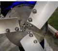
=>PERMANENT MAGNET DC MOTOR (max voltage=40V, max current=4.4A, RPM=450)
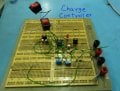
=>555 timer based Charge Controller from (mdpub.com/555Controller/)
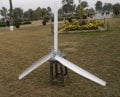
=>PVC Blades 1meter radius
=>14 feet high assembly for elevation
=>12V 20AH lead acid dry battery
Everything is ready , charge controller is working fine except the following question which is irritating my mind.. PLZ ANYONE CAN HELP ME OUT THIS
....IS it compulsory that battery should be charged with uniform current?? because wind power is always varying that produce varying current!!! my biggest problem is to identify the component in my 555 charge controller that regulates the varying current to uniform to charge the my 12v 18AH battery...(I have made 555 timer based charge controller from mdpub.com/555Controller/... furthur more i have noticed that this charge controller is more of a switching device that switches dump load on and off when required rather than a "CHARGE CONTROLLER").... plz respond!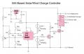
I have done 90% of the work.. I m using the following components
=>PERMANENT MAGNET DC MOTOR (max voltage=40V, max current=4.4A, RPM=450)
=>555 timer based Charge Controller from (mdpub.com/555Controller/)
=>PVC Blades 1meter radius
=>14 feet high assembly for elevation
=>12V 20AH lead acid dry battery
Everything is ready , charge controller is working fine except the following question which is irritating my mind.. PLZ ANYONE CAN HELP ME OUT THIS
....IS it compulsory that battery should be charged with uniform current?? because wind power is always varying that produce varying current!!! my biggest problem is to identify the component in my 555 charge controller that regulates the varying current to uniform to charge the my 12v 18AH battery...(I have made 555 timer based charge controller from mdpub.com/555Controller/... furthur more i have noticed that this charge controller is more of a switching device that switches dump load on and off when required rather than a "CHARGE CONTROLLER").... plz respond!