Facebook
 Google
 GitHub
 Linkedin
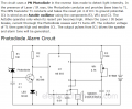
I have made this circuit http://electroschematics.com/search...ious/alarm/page/2/&ss=&siteurl=/J:/Photodiode Alarm circuit.htm&ref=&ss=&siteurl=/J:/Photodiode Alarm circuit.htm&ref=&ss=
but there is a problem, the alarm still work in two cases because the voltage on pin 4 "rest" even if i don't attach any wire with it is about 0.92 volt (alarm on), so is there a problem in ic 555 or what????
but there is a problem, the alarm still work in two cases because the voltage on pin 4 "rest" even if i don't attach any wire with it is about 0.92 volt (alarm on), so is there a problem in ic 555 or what????