555 monostable help

Thread Starter

Madaxe

Joined Sep 11, 2023
15
That sounds correct, so I can't tell you why it doesn't work.
All that I know is that it should.
I will try again with a fresh start. I'm about to head into the electronics store now and get a full set of supplies to start again from scratch. i'll stick to breadboard this time so I can make changes easily. last time, I started on breadboard, go the timing and output working and soldered it straight to perfboard, then discovered the problem. I'll be less hasty this time around.
 

Thread Starter

Madaxe

Joined Sep 11, 2023
15
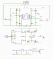
Hi Everyone, I would like to thank you for your help. It is now working perfectly. I made two changes to the original schematic, firstly by adding an R/C Network to the reset pins, and then by changing the timing capacitor to go from V+ to the Node at the Threshold and Discharge pins.

I'm not sure what went wrong last night and this morning, but when I started from scratch on a breadboard, it worked perfectly from the start. I currently have an LED in place of the output section, but I will build the H-bridge now and make sure it works then I'll get some PCB's made and send off for testing.

If anyone has any comments on the H-Bridge I'd certainly love your feedback. the one I've drawn is just a verbatim copy of a controller i have on my desk which I've traced out and added to the schematic, I'm not 100% certain it correct, but I am unable to get those particular Mosfets locally, so I'm looking to test with the only mosfest available to me right now which is: IRF540 and IRF9540N which I have for some unknown reason. I'll go through the data sheets to make sure they will work before powering them up, but failing that, when I do go to getting some boards made, can anyone point me towards somewhere I can choose the best Mosfets for the purpose? in this instance I only need say 5 Amps, but it would make sense to have them rated much higher in order to make sure there are not overheating issues. I have trolled through so many datasheets, and there's so many to choose from, I'm in a fog now. Obviously, I'd like to use the most common components available, so if anyone know a good combination of N and P channel Mosfets which can handle the task, I'd appreciate your input.

As per some previous comments, in the event of a limit switch failure, the motor will obviously draw a lot more current once the arm reached the mechanical stop, so oversizing the Mosfets is a good idea, how much? I don't know because I haven't been able to replicate that condition yet to find out how much current it will draw in that situation, but I think that it opens up another question for fuse sizing. Obviously, the fuse needs to be small enough to protect the cabling, but large enough that it won't blow if the limit switch fails and the motor reaches it's mechanical stop for the 0.5 seconds or so until the timer times out, but then, the Mosfets need to be suitably sized so they don't overheat in that same scenario.

Man Electrical Engineering is intense, as soon as you solve one problem, 10 more show up, I'm glad I did Mechanical.

for anyone wondering, and for future readers, the working (timer circuit only) schematic is attached.

I cannot thank you all enough. honestly, I feel great having found the right people to ask. I wish I could help you all the way you've helped me.
 

Attachments

Last edited:

crutschow

Joined Mar 14, 2008
38,572
the Mosfets need to be suitably sized so they don't overheat in that same scenario.
You really need to get some reasonably close idea of the operating and stall currents for the actuator to properly size the MOSFETs and fuse.
Man Electrical Engineering is intense, as soon as you solve one problem, 10 more show up, I'm glad I did Mechanical.
Interesting.
And one of the reasons I went into Electrical instead of Mechanical Engineering, is because I though it would be generally easier to correct a mistake in a new electrical design as compared to a new mechanical design.
 

Thread Starter

Madaxe

Joined Sep 11, 2023
15
You really need to get some reasonably close idea of the operating and stall currents for the actuator to properly size the MOSFETs and fuse.
Interesting.
And one of the reasons I went into Electrical instead of Mechanical Engineering, is because I though it would be generally easier to correct a mistake in a new electrical design as compared to a new mechanical design.
Thanks Zapper, I will pull one of the actuators apart this coming weekend and bypass the limit switches and run it to a stop to measure the real current, I have a few of them cluttering up my desk, it wouldn't hurt to destroy one so it can be discarded. once I know what the max current draw is, how would you correctly choose a rating for mosfets and fuses from that figure? is there a formula, industry standard, or a rule-of-thumb that is typically used? I would normally take the yield point, reduce it by a safety factor percentage, than create a predetermined failure node at the point, I assume fusing has a similar principal.

also, just to throw a spanner in the works, I gave the client an update on my control idea yesterday afternoon, and he informed me they also want a manual over-ride, so they can use a switch to extend and retract the arm for manual operation (they want to utilize the same arm across the entire fleet with differing control scenarios). From what I can tell, the switch will enable a variety of functions (flashing lights, dust suppression, etc.) as a "engagement mode" and "idle mode" scenario. any ideas how I could add a manual override into the circuit? from what he explained, it would be a two position toggle switch, one position for up, and one position for down. I can't see a way to add that functionality with the existing circuit, I told him just to use two-relays, but then there is still the safety issue of power going to the unit at all times, which was the whole point of this circuit to begin with.

is it possible to create a momentary trigger signal from a change in state of a mechanical switch? so if a switch is switched on, it will send a single pulse once, then when it is switched off it will send another pulse once? I had a quick google last night and couldn't come up with anything. any ideas?
 

crutschow

Joined Mar 14, 2008
38,572
correctly choose a rating for mosfets and fuses from that figure?
You should pick a fuse that can handle the stall current, and pick a MOSFET with a low enough on-resistance so it doesn't dissipate more than about 1 watt with the stall current.
is it possible to create a momentary trigger signal from a change in state of a mechanical switch?
Sure.
You add a capacitor in series with the input of the 555 trigger transistor.
This will give a decaying pulse with a time-constant equal to the capacitor value times the transistor base resistor.
The pulse only has to be long enough to trigger the 555 so with a 1kΩ input resistor, a 100nF capacitor should be large enough.
 

Thread Starter

Madaxe

Joined Sep 11, 2023
15
You should pick a fuse that can handle the stall current, and pick a MOSFET with a low enough on-resistance so it doesn't dissipate more than about 1 watt with the stall current.
Sure.
You add a capacitor in series with the input of the 555 trigger transistor.
This will give a decaying pulse with a time-constant equal to the capacitor value times the transistor base resistor.
The pulse only has to be long enough to trigger the 555 so with a 1kΩ input resistor, a 100nF capacitor should be large enough.
WOW... I am trying to visualize this, but you've just blown my mind. I am trying to get my head around it.
 

MrChips

Joined Oct 2, 2009
34,946
This RC circuit is recognized as a high pass filter.

1694651047183.png

It is also a differentiator. In other words, it takes the derivative of the input signal, i.e. the output is proportional to dV/dt.
You can use this to convert a long press of a push-button to a short duration pulse. Hence it overcomes the problem of someone holding the button down forever.
 

crutschow

Joined Mar 14, 2008
38,572
I am trying to visualize this
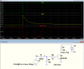
Below is the sim of an example circuit with the transistor, for a step voltage input as a switch would generate.
I added R3 to drain the last of the capacitor charge, since otherwise the transistor turn-off had a long tail.

1694651095812.png
 

Thread Starter

Madaxe

Joined Sep 11, 2023
15
This RC circuit is recognized as a high pass filter.

View attachment 302743

It is also a differentiator. In other words, it takes the derivative of the input signal, i.e. the output is proportional to dV/dt.
You can use this to convert a long press of a push-button to a short duration pulse. Hence it overcomes the problem of someone holding the button down forever.
Interesting. not sure how that would work in my circumstance. I think that's a little bit above my electrical understanding. I know (a little) about high-pass filters from building and modding guitar and bass amps, i understand how they work in AC signals to alter the frequencies "passed thru" to the next part of the circuit, but there's a mental block that's stopping me from understanding it's use in this circumstance. I kinda feel like I could think of it more as a coupling capacitor, to block DC from the circuit (even though it's a DC Circuit), but it's just sitting there in my head not progressing to the next part of the understanding process. I went from feeling like I was finally understanding electrical engineering principals, to feeling like the dunning-kruger effect just hit me in the face with a brick.

I'm not going to be able to concentrate on anything now for the rest of the day until I understand this concept.
 

MrChips

Joined Oct 2, 2009
34,946
I will try to make it easy for you. If you understand high pass filters then that's all you need to know.
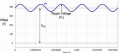
All signals are DC + AC. In other words, you can have an AC signal superimposed on top of a constant DC voltage.

Here is an example of a DC + AC signal.

1694652826408.png

A capacitor in series with the signal is a DC blocking capacitor, yes?
Another way of putting it, it passes the AC component and blocks low frequencies all the way down to DC.

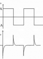
When a push button is pressed and released, the RC high pass filter responds to the step or changes. The DC part is blocked (i.e. removed). You get positive going and negative going spikes at the make and break of the push button (depending on how your push button is wired).

1694653241640.png

Now you need to decide which side of the button action you want to have an effect, on the positive spike or on the negative spike, on the press or on the release?

If the resistor in the RC circuit is tied to GND, then the negative spike will have no effect in your circuit. The circuit will respond to the positive spike only.

If the resistor in the RC circuit is tied to +5V, then you have raised the baseline to +5V. In this case, the negative spike is the one to trigger the next circuit.
 

crutschow

Joined Mar 14, 2008
38,572
i understand how they work in AC signals to alter the frequencies "passed thru" to the next part of the circuit,
You need to stop thinking about frequencies here (frequency-domain), and instead think in time (time-domain), as in MrChips diagram for the square-wave input, which shows the signal versus time.

The time-width of the spikes is determined by the RC time-constant of the circuit.
For an RC circuit the output voltage changes by ≈0.632 of the previous value for an increment of time equal to one time-constant (discussed here).

Understanding that will go a long ways to help you understand how the circuit works.
 

Thread Starter

Madaxe

Joined Sep 11, 2023
15
You need to stop thinking about frequencies here (frequency-domain), and instead think in time (time-domain), as in MrChips diagram for the square-wave input, which shows the signal versus time.

The time-width of the spikes is determined by the RC time-constant of the circuit.
For an RC circuit the output voltage changes by ≈0.632 of the previous value for an increment of time equal to one time-constant (discussed here).

Understanding that will go a long ways to help you understand how the circuit works.
I've build and modded hundreds of amps (as a passionate hobby) over the years, predominantly valve amps, and I thought I understood the theory of capacitors until now, I feel like I've learned more in the last few hours than I have in 20 years previous.

And I completely understand what you're saying now, I just had to relay it back to something I understand.

Potentially, I could use their on-off toggle switch, and have one trigger of the NE556 biased positive, and the other trigger biased negative, so when they switch on the whole circuit (flashing lights, dust suppression, etc.) with the toggle switch, the positive switching could trigger the arm to extend, and when they switch it off, the negative switching could trigger it to retract.

I've got a big urgent job on today and tomorrow, but on the weekend I will revisit this.

Zapper and MrChips, you are wonderful people. The world is a better place with people like you around. Thank you so much.
 
Top