Facebook
 Google
 GitHub
 Linkedin

Hello.
Iam presently working on designing a basic multi level inverter.
Iam not explaining the working principle of the inverter.
I have a plan in which a few timers(555) are cascaded.
The process will be first initiated by a 555 astable whose duty cycle is 10%.
(5ms ON and 45ms OFF). the time period is 50ms.
For every 50ms, the process should repeat.
Now coming to the point, the first section timer should give a 15ms ON pulse.
This should be initiated by the astable 555 after 5ms.
Thats why i wired the astable to have 5ms ON pulse.
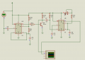
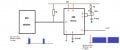
when i connected the output (3 pin) of astable 555 to triggering input (2 pin) of monostable 555, the output is simply inverting the triggereing signal.
Chek the attachment.
When iam varying the 47K pot also, the output(555 mono output) is not responding. The output is responding when iam adjusting the attributes of 555 astable.
Why the timing elements of 555 mono are not playing the role.
Iam presently working on designing a basic multi level inverter.
Iam not explaining the working principle of the inverter.
I have a plan in which a few timers(555) are cascaded.
The process will be first initiated by a 555 astable whose duty cycle is 10%.
(5ms ON and 45ms OFF). the time period is 50ms.
For every 50ms, the process should repeat.
Now coming to the point, the first section timer should give a 15ms ON pulse.
This should be initiated by the astable 555 after 5ms.
Thats why i wired the astable to have 5ms ON pulse.
when i connected the output (3 pin) of astable 555 to triggering input (2 pin) of monostable 555, the output is simply inverting the triggereing signal.
Chek the attachment.
When iam varying the 47K pot also, the output(555 mono output) is not responding. The output is responding when iam adjusting the attributes of 555 astable.
Why the timing elements of 555 mono are not playing the role.
Attachments
-
 41.3 KB Views: 19