555 MMV with TTL signal as input

Thread Starter

Andreas

Joined Jan 26, 2009
90
Hello fellow AAC pundits,

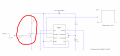
I have a query regarding triggering a 555 MMV using a Negative edge triggerd TTL pulse.

I have had this working successfully without the front end components (circled in red) but I feel the circuit may become unreliable as the battery voltage drops due to the fact that the TTL pulse is very close already to the trigger threshold of 4V [<(V+)/3].

Clearly using a PNP isn't going to work in the configuration as the TTL Voltage can't go below ground. I have considered NPN, Hex Inverter and Optocoupler ideas but would like some better more elegant ideas and suggestions to do this.

Thank you,
Andreas
 

Attachments

ebp

Joined Feb 8, 2018
2,332
Just passing for a minute & haven't thought about this:

NPN common-base with base biased a couple of diode drops above ground?
 

crutschow

Joined Mar 14, 2008
38,550
Below is the LTspice simulation of a circuit using one NPN transistor in a common-base circuit that should work.
If you have 5V available, you can use the circuit on the left.
If not, use the one on the right.

upload_2018-3-9_17-56-17.png
 
Last edited:

Thread Starter

Andreas

Joined Jan 26, 2009
90
Below is the LTspice simulation of a circuit using one NPN transistor in a common-base circuit that should work.
If you have 5V available, you can use the circuit on the left.
If not, use the one on the right.

View attachment 147999
The 5V TTL pulse is coming from a 3rd party device.
It's essentially just an inverting level shifter that I require and I think SG's reply above yours looks simple and effective.

Tnx
 

Thread Starter

Andreas

Joined Jan 26, 2009
90
You said you needed a level shifter, not a inverter.
SG's circuit is a non-inverter (as is mine).
Yes I noticed that from your diagrams and it did make me curious. Perhaps I didn't make myself clear enough. The output always needed to be level shifted and inverted. It was really about how I build a reliable front-end to deal with a negative edge TTL pulse esp. with a supply Voltage greater than it or any DC supply voltage (within spec) for that matter.
Thanks for your input , I appreciate your comments and ideas.
Andreas
 

sghioto

Joined Dec 31, 2017
8,634
Getting back to the logic in post #1 why should you need any additional components? As the Vcc voltage drops on the 555 so does the voltage required to keep the trigger above 1/3 Vcc.
SG
 

ebp

Joined Feb 8, 2018
2,332
There was a request for "more elegant." A common base switch is elegant and carefully applied as part of a cascode configuration (what crutschow proposed, although the bottom of the cascode pair is not shown as such) can be used to switch kilovolts and/or very large currents. I don't think it is very commonly used, probably less-so now that there are high voltage FETs and IGBTs available, but it is a circuit worth remembering. It is also very useful in analog applications.
 

Thread Starter

Andreas

Joined Jan 26, 2009
90
Then just use a single NPN transistor with its emitter grounded, the base resistor to the TTL signal, and the collector resistor to +12V.
The TTL pulse stays in a high state until triggered (by the operator) at which point it goes Low for a few 100ms. The problem I see with your idea (as was my initial idea too) is that pin 2 will be pulled to gnd all of the time until the pulse is at 0V. SG has the logic correct.
 

Thread Starter

Andreas

Joined Jan 26, 2009
90
Getting back to the logic in post #1 why should you need any additional components? As the Vcc voltage drops on the 555 so does the voltage required to keep the trigger above 1/3 Vcc.
SG
Yes I see where you are coming from and I did think that too as I wrote in my opening brief. I wanted something reliable and felt that a 5V TTL pulse (or 4.6V ish in my case) was simply getting too close to 1/3 VCC especially with a fully charged battery.
I liked your inverter using two NPNs and had I have had the time, I may have come to that result too. It was a crazy week and I had literally 30 mins to knock this up, test it and implement it before it was needed. As I said previously. My circuit did work but for future reliability I will modify it and actually solder th ecomponents onto a piece of vero board.
Tnx again
 
Top