555 LED dimmer

Thread Starter

Sharpen047

Joined Apr 19, 2012
51
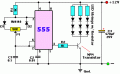
Hey guys ive been working on a dimmer for some Lights that are going into a trailer for lights over an oven. I have been working on the circuit for about two weeks and couldnt figure out what the problem was. I followed the schematic here:
http://www.reuk.co.uk/LED-Dimmer-Circuit.htm
It doesnt really tell me what i need to know as far as frequencies or power ratings.
It says to have a 1k resistor between pin 3 and the transistor( i used FJE3303H2TU-ND) because i will have more than 600 MA going through the circuit to replace the fluorescent bulbs. i have the circuit working but at about half brightness of the leds the timer gets super hot and i was wondering if anyone knew if it was from not running a 1k resistor between the chip and the transistor. If i put that resistor back in, the leds are always on.
I am trying to learn these things myself in my spare time and dont understand the gains or frequencies involved in this ciruit and how they interact with each other.
I am using an NE555 texas instruments chip.
I would appreciate any help, Thanks!
 

Thread Starter

Sharpen047

Joined Apr 19, 2012
51
I am going to try 150 at 2 w Thanks a bunch and will see if i can calculate how you got 150. I am using super flux leds 1.9 vf 20ma and 7 - to + of the next led with a 5.6 ohm resistor and 13.4v.
i was told not to use a mosfet because those are for motors and i dont know enough about gates, i just went to the most popular led dimmer circuit on google.
Its my first attempt at anything past replacing stereo wire or wiring a car stereo.
Thanks a ton for the help!
 

wayneh

Joined Sep 9, 2010
17,496
i was told not to use a mosfet because those are for motors and i dont know enough about gates
Learning opportunity: A MOSFET would actually be a good choice here. They're just a special type of transistor, with a couple of great properties. First, unlike the BJT "normal" transistor, they don't require a current on their gate pin, only a voltage. That's often much easier to design for. Secondly, when fully on, they have very little resistance and as a result, stay cooler with less heat sinking.

Your BJT will probably be fine, but don't shy away from a MOSFET based on dubious advice.
 

Thread Starter

Sharpen047

Joined Apr 19, 2012
51
So why wasnt a MOSFET used in the original schematic? what is the draw back?
If it only requires voltage that wouldnt put any stress on the 555, right? I have to order more parts anyway i could just replace the transistors with MOSFETs.
Also what kind of MOSFET would i want? My thinking was to get a giant transistor so it would run cooler. Rating at well over an amp and im running less than half of that. Like the resistors, i will probably get 5w because the calc says i will be running 5.5 watts of power through the transistor (just for it to run cooler , i know the power doesnt go through pin 3.)
 

wayneh

Joined Sep 9, 2010
17,496
So why wasnt a MOSFET used in the original schematic? what is the draw back?
The main drawback is not a problem in this circuit; a MOSFET needs enough voltage to turn on. A "regular" MOSFET needs at least about 10V on the gate. Hard to say why they didn't choose a MOSFET in the circuit. Maybe cost? But MOSFETs certainly aren't costly.
If it only requires voltage that wouldnt put any stress on the 555, right?
Right! The gate is a capacitor, so at high frequency it can require a lot of current to keep charging and discharging. Again, not a problem in this circuit. [edit] Actually, I didn't do the math to verify. But if it's OK for a motor, it's OK for LEDs.
Also what kind of MOSFET would i want? My thinking was to get a giant transistor so it would run cooler. Rating at well over an amp and im running less than half of that.
There are tons of choices. I've got a bag of IRF540N mosfets that I use for general purpose, and one of those would be more than enough for this application. I believe the IRF510 is available at Radio Shack, and would also work. Just get one rated for at least about 4X more than your expected current.
 
Last edited:

Thread Starter

Sharpen047

Joined Apr 19, 2012
51
to tracecom: The exact schematic is the one on the link with the LEDs.
I am positive that it is done correctly because it works.
I am looking for a MOSFET rated in continuous current gain right?
Would a MOSFET be a better option than a gate or vice versa?
I am trying to make this circuit as reliable as possible.
 
Last edited:

wayneh

Joined Sep 9, 2010
17,496
I am looking for a MOSFET rated in continuous current gain right?
You need to look at the rating for continuous current (not peak, which is huge). The max continuous current is usually under ideal conditions that few of us ever achieve, for instance with a huge heat sink. That's why I always look for at least 2X more rating than I intend to have in the circuit. More is better, and high current handling adds very little to cost.
Would a MOSFET be a better option than a gate or vice versa?
Well, a "gate" is one of the pins on the MOSFET, so I don't quite understand the question. A MOSFET is an excellent choice for just about any circuit where you are handling power. If you're asking about "logic gates", that's another thing altogether and not relevant to this application.
 

Thread Starter

Sharpen047

Joined Apr 19, 2012
51
ok so i plugged the circuit and panel of leds in to the bi pin base and turned the switch on and the leds did not turn on, double checked wiring and parts with no luck. i tested voltage at the circuit in terminals and it read 11.75v. I hooked it up to a power adapter (12v dc) and the circuit worked fine. output of the adapter is higher than 12v, its around 14 which i designed the array for. Could the voltage be too low for 7 1.9v leds?
 

wayneh

Joined Sep 9, 2010
17,496
Can't quite understand without a schematic, but the short answer is yes, below a cutoff level (Vf min), LEDs won't light at all. You may need to use one less LED in series and increase slightly the value of your current limiting resistor.
 

Thread Starter

Sharpen047

Joined Apr 19, 2012
51
Alright just tested with the generator running at 13.7v and the transistor started smoking. i found a 16v power adapter for some wireless headphones as a test with a new transistor and they lit up fine, and they were dimmable. circuit is done correctly, i even tried a separate circuit made with the same model everything, wired the same way and they still dont light up. i calculated the minimum vf for the LEDs to be 13.3v for 7 with a 5.6 ohm resistor.
I have 6 rows of 7 leds each. none work when in the trailer.
I cant stay at my friends house so ill be running power from my car battery so i know the power system works correctly.
 

Thread Starter

Sharpen047

Joined Apr 19, 2012
51
ok the switch is a two way switch meaning one is on when the main light in the trailers is on and one is when you flip the switch for the fixture itself. I am wondering if it would matter if the transistor was on the positive side to be dimmer when the fixture switch is flipped and full when the main is turned on. There is another 12v wire for the main light to the back of the fixture. Would that kill the transistor?
 

#12

Joined Nov 30, 2010
18,224
Do not change where the transistor is connected. Way more complications than I want to deal with a this time.

First, the time constant caused by C1 and P1 (the 50k potentiometer) calculates to 178 cycles per second, which is way faster than a human can see. It will appear that the LEDs are on at half brightness and never turn off (when it is working correctly). I suggest changing the capacitor to 10uf to slow this down to about 1.8 blinks per second.

Second, the way to calculate the resistor that drives the transistor is to assume you need one tenth of the load current to slam the transistor fully on and fully off. Six rows of LEDs at .02 amps each is .12 amps. You need to hit the transistor with .012 amps at its base. Allowing a volt or 2 of loss in the 555 chip and the base to emitter circuit, 12V/.012 amp is 1000 ohms. (The original circuit is correct. I must have slipped a digit.) Because this circuit can do 98% "on" time, you calculate the wattage as (12V squared over 1000) times 98% = .141 watts. Always use bigger wattage than you need, so 1/4 or 1/2 watt will work for the 1000 ohm resistor. (Bigger is more reliable.) Use 1/2 watt (or larger) for good reliability.

Third, the most likely cause of a smoked transistor is that you hooked it up backwards.

Fourth, LEDs are not like resistors or incandescent light bulbs. They don't work from giving them enough voltage, they work by giving them enough current, and even that has a fudge factor. The "breakover" voltage of an LED increases a little bit as the current goes up. What you want to do is calculate AT LEAST one less LED than the available voltage can breakover, and then add a resistor that will limit the current to .02 amps.

For lowest available voltage = 12, you figure 12V/1.9V = 6.3 LEDs.
Hook up 5 LEDs for a "leftover" voltage of 2.5V
Then allow .04 volts for the collector to emitter saturation voltage of the transistor (Fig. 3 in the datasheet)
2.46 leftover Volts / .02 amps = 123 ohms in each string of LEDs.
Because .02 amps is the Maximum for most LEDs of this size, use the next larger amount of resistance, 150 ohms.
P = I squared R
P = .02 squared times 150 = .06 watts
the 150 ohm resistors will need to be at least 1/8th of a watt.

The MOSFET is not about current gain. It's a variable resistor, but not a very convenient one. Not a problem in this case, we only want it ON of OFF. You do that by applying between 10 and 20 volts to its gate. When the gate goes positive, the MOSFET turns into a resistor that is often way more efficient than a bipolar junction transistor. The IRF510A collapses to .4 ohms for a voltage loss of .4 x .12A = .048V
Not an improvement over the FJE3303 at .04 volts loss (collector to emitter).

Please allow that I make mistakes, and there are a lot of chances to make a mistake in this much writing.
 

Attachments

wayneh

Joined Sep 9, 2010
17,496
I know that's what the OP followed, but I'm pretty sure he's made some modifications (7 LEDs in series, 6X) and I can't follow the 2-way switch he's asking about.
 
Top