What is the COM terminal used for on a 220V 10000W Dimmer variator?

Thread Starter

brian15ignacio

Joined Jul 30, 2025
2
Hi everyone,

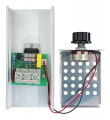
I’m using this 220V 10000W dimmer module:
https://rambal.com/control-de-potencia/1416-dimmer-regulador-220vac-10000w.html

I’ve connected:
  • IN+ to AC mains (220V),
  • OUT to a 220V motor (inductive load),

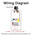
But the module has another terminal labeled COM, and I can’t find any documentation explaining its purpose.

Is it:
– a common ground for an external potentiometer?
– a signal ground for a remote control input?

I’m using the dimmer manually right now (with its onboard buttons), and it seems to work fine without connecting anything to COM. But I want to be sure before attempting external control.

Any help would be greatly appreciated!
 

MaxHeadRoom

Joined Jul 18, 2013
30,598
I would assume it is the common for both IN & OUT, being what looks as though it is just a non isolated dimmer unit.
So what are you using for the relative common at the moment?
Measure in - out relative to COM.
 

Thread Starter

brian15ignacio

Joined Jul 30, 2025
2
I would assume it is the common for both IN & OUT, being what looks as though it is just a non isolated dimmer unit.
So what are you using for the relative common at the moment?
Measure in - out relative to COM.
Thanks again. I've attached a wiring diagram that matches the module I'm testing.

As you can see, the COM terminal is marked as optional:
"COM is a common terminal; it may or may not be connected."

In the diagram, the dotted lines from COM point to the potentiometer, not the power circuit.
This confirms that COM is a signal reference (ground) for the internal control; it has no relation to the power return or the load.
As far as I can tell, the COM terminal is not connected to the AC neutral line or the load return path. It appears to be the ground reference for the internal control circuit, specifically for the potentiometer that adjusts the triac's firing angle.

Currently, I'm connecting:
AC active (L) to INPUT+
Load between OUTPUT and AC Neutral (N) directly

So the load path is:
L → INPUT+ → regulator → OUTPUT → Load → N

I'm not using COM for the load path. It appears to be isolated (logically, not galvanically) and is only used for the potentiometer.
If you trace the PCB, COM goes to the RC trigger circuit, not the load.
 

Attachments

Ian0

Joined Aug 7, 2020
13,114
It is probably just there to allow a convenient point to connect the input neutral to the output neutral.
What is SHOULD be is a connection for the filtering components, but they are conspicuous by their absence. I bet you'd have trouble obtaining a EMC certificate, and if you did, it would probably be a fake.
Don't run it anywhere near any equipment that is susceptible to electromagnetic interference.
 

ericgibbs

Joined Jan 29, 2010
21,419
hi Brian,
It is wired like this>

CAUTION.

On the version I had the Potentiometer tags were at Mains voltage.
Do you have any means of testing the isolation of the potentiometer and its wiring???

E
Image1.jpg
 
Last edited:

Ian0

Joined Aug 7, 2020
13,114
hi Brian,
It is wired like this>

CAUTION.

On the version I had the Potentiometer tags were at Mains voltage.
Do you have any means of testing the isolation of the potentiometer and its wiring???

E
View attachment 353386
Its inevitable that the potentiometer tags will be at mains potential. How many potentiometers have you come across that will pass a 1.5kV flash test between terminals and case?
 

ericgibbs

Joined Jan 29, 2010
21,419
Hi,
My cautionary note to the TS, was not just have the Pot 'dangling' in mid-air, which would run the risk of the TS touching the tags.
The pot body should be mounted inside a suitable enclosure.

@Ian, not sure what point you were trying to make, with your post ?

E
 
Top