555 and flyback not the same frequency?

Thread Starter

magnet18

Joined Dec 22, 2010
1,227
Looks like your 'scope probe doesn't have a good ground? The signal appears to be going negative, and it shouldn't do that.
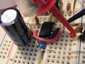
I can't see why, it's connected directly to the ground line on the breadboard... It may be an effect of the capacitors or the flyback, but I''m the one asking for the help, so I don't know.

I count ~22.5 divisions out of 25; so that's 0.9*200uS = 0.00018 = 5.555kHz.

The frequency's being counted from the "T" marker to some unknown point - I guess you have x5 or x10 enabled?

It could be that your 555 ground terminal or MOSFET source terminal ground path isn't very good?
not that I can tell. if there is it's less than one tenth of an ohm. I let it sit for awhile and collected another sample, this time with the probe ground right on pin one of the 555, I also collected data on channel 2 across the timing cap, I don't know what's happening during the portion in the screenshot, it blows my mind, it might be a glitch?? but after it continues as normal. everything seemed alright this time (with the exception of smoke from under the flyback, is superglue conductive?)

I went ahead and attached the text file of the data, I don't know if you'll be able to easily reconstruct a graph with software similar to mine or not, but if you can it should help as you'll be able to see the whole sample instead of a screenshot
in any case, it might help those in the future.

As for the frequency recording, I'm not sure where it measures to, I don't see it as a setting anywhere, I'll have to find the users manual and look it up.

[EDIT]
It would appear that the text file is too large... Oh well *shrug
 

Attachments

Last edited:

SgtWookie

Joined Jul 17, 2007
22,230
I don't know HOW you managed to get those waveforms from across the timing cap (pins 2, 6) and the output (pin 3). Perhaps your 'scope is "glitchy". It looks as if channels 1 and 2 were swapped in the middle.

I don't know whether Superglue is conductive or not; I only suspect it has a fairly high insulation value, but it isn't advertised as such.
 

Thread Starter

magnet18

Joined Dec 22, 2010
1,227
I don't know HOW you managed to get those waveforms from across the timing cap (pins 2, 6) and the output (pin 3). Perhaps your 'scope is "glitchy". It looks as if channels 1 and 2 were swapped in the middle.
It's possible, but if it ever happens again and I verify that it was accurate I'll let you and Bill know. Its odd, I've never had a problem with it before... High voltage does funny things I guess, if theres an electrical field strong enough to feel in the hairs all the way up my arm I guess it can flip/flop o-scope probe channels. If you want I can e-mail you the data file or break it into smaller segments for upload.

I don't know whether Superglue is conductive or not; I only suspect it has a fairly high insulation value, but it isn't advertised as such.
I can tell you its slightly conductive when still a bit wet, and it burns a bright yellow and smells absolutely awful;) (lets just say I'm glad I have two flybacks):rolleyes:
 

jpanhalt

Joined Jan 18, 2008
11,087
Do you have a second source of 12V, even a small 12V battery for remotes? I would try powering the 555 (only needs low current) from the second source. Keep the grounds common between the 555 and mosfet parts.

What does pin 3 look like on an expanded scale?

John
 

Thread Starter

magnet18

Joined Dec 22, 2010
1,227
Do you have a second source of 12V, even a small 12V battery for remotes? I would try powering the 555 (only needs low current) from the second source. Keep the grounds common between the 555 and mosfet parts.
I have a second 12V marine battery, I'll give that a shot

What does pin 3 look like on an expanded scale?

John
the scope data?
I can collect a sample on the 50uS setting if thats what you mean
 

Thread Starter

magnet18

Joined Dec 22, 2010
1,227
Here it is on the 50uS scale, with the 555 still powered on the same battery (the second one is charging)
5 turns of 18ga magnet wire on the primary, gap distance 3.16mm/.124in
I've changed from the TV flyback to a smaller one out of a CRT monitor, it seems to actually work better, at least it's silent (and not smoking:rolleyes:)

I captured the part with the worst interference, and the voltages took some time rising before they leveled off at 10 V(battery at 11.46).
 

Attachments

jpanhalt

Joined Jan 18, 2008
11,087
Let's see if the pin 3 wave improves with a separate supply.

How's history coming?

I have to play farmer rest of this morning and can't be back until late afternoon.

John
 

Thread Starter

magnet18

Joined Dec 22, 2010
1,227
Heres the shot of it with the second battery, looks beautiful to me :D
(with the exception of the glitchy bit at the beginning, but it's better than it was)
my scopes frequency measurement seems to be acting funny, when I have both channels on it looks like it doubles the frequency... I tried with just one channel on and got a 25kHz reading.
Thats what you have to deal with when you get the cheapest scope possible :rolleyes:
 

Attachments

SgtWookie

Joined Jul 17, 2007
22,230
Now you seem to be getting about 10v out of pin 3 when high. Before, it looked like it was only around 8v.
The timer cap signal looks just a tad "glitchy" on top. Do you have a 0.1uF and 1uF (or larger) caps across the Vcc/GND pins of the 555 timer?

You show a 10nF cap from pin 5 to ground; are it's leads as short as possible?
 

Thread Starter

magnet18

Joined Dec 22, 2010
1,227
Now you seem to be getting about 10v out of pin 3 when high. Before, it looked like it was only around 8v.
The timer cap signal looks just a tad "glitchy" on top. Do you have a 0.1uF and 1uF (or larger) caps across the Vcc/GND pins of the 555 timer?
.1uF AND 1uF?
How should the two be arranged, just in parallel at the same place?
I currently have a 1000uF running from the pin 8 to the ground line on the breadboard right next to where pin 1 on the 555 enters the ground line... if that makes sense
(want picture??)

You show a 10nF cap from pin 5 to ground; are it's leads as short as possible?
yesh, but it's a breadboard, so theres excess metal and capacitance going haywire everywhere...
 

SgtWookie

Joined Jul 17, 2007
22,230
Yes, you should have an 0.1uF metal poly film, ceramic, etc. cap across the Vcc and GND pins, with the leads as short as possible. You also need a 1uF or larger cap in parallel with the 0.1uF cap, but it doesn't have to be right on top of the IC. It should be very close by, though.
 

Thread Starter

magnet18

Joined Dec 22, 2010
1,227
Yes, you should have an 0.1uF metal poly film, ceramic, etc. cap across the Vcc and GND pins, with the leads as short as possible. You also need a 1uF or larger cap in parallel with the 0.1uF cap, but it doesn't have to be right on top of the IC. It should be very close by, though.
Alright, will do
Is this because of the different resistance values of the caps?
 

jpanhalt

Joined Jan 18, 2008
11,087
Now that your 555 driver is working better, what does the wave look like at the drain of the mosfet? Start with a relatively high voltage setting for your scope, say 100 V, then decrease until you see the waveform.

John
 
Top